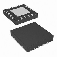
ISL8107IRZ Intersil, ISL8107IRZ Datasheet

ISL8107IRZ
Specifications of ISL8107IRZ
Available stocks
Related parts for ISL8107IRZ
ISL8107IRZ Summary of contents
Page 1
... PART NUMBER (Note) ISL8107IRZ ISL8107IRZ-T* ISL8107 IRZ *Please refer to TB347 for details on reel specifications. NOTE: These Intersil Pb-free plastic packaged products employ special Pb-free material sets, molding compounds/die attach materials, and 100% matte tin plate plus anneal (e3 termination finish, which is RoHS compliant and compatible with both SnPb and Pb-free soldering operations) ...
Page 2
Block Diagram INT. BIAS VOLTAGE INT. BIAS VOLTAGE - 0.77V + EN/SS SGND VBG PGOOD - 1.345V + 1.03V INTERNAL REGULATOR POWER-ON RESET (POR) SOFT-START AND FAULT LOGIC + REFERENCE + 1.192V REF EA ...
Page 3
Typical Application 75V Filter VCC RT/ SYNC PGOOD VBG C BG EN/ ISL8107 D BOOT C F1 PVCC VFF BOOT R OCSET OCSET C ...
Page 4
Typical Application 75V RT/ VCC V CC < VFF C F2 SYNC PGOOD VBG C BG EN/ ISL8107 D BOOT C F1 PVCC VFF BOOT R OCSET ...
Page 5
... Enable Threshold 5 ISL8107 Thermal Information Thermal Resistance (Typical) QFN Package (Notes Maximum Junction Temperature . . . . . . . . . . . . . . . . . . . . . +150°C Maximum Storage Temperature Range . . . . . . . . . .-65°C to +150°C Pb-free reflow profile . . . . . . . . . . . . . . . . . . . . . . . . . .see link below http://www.intersil.com/pbfree/Pb-FreeReflow.asp SYMBOL TEST CONDITIONS I UGATE open VCC I VCC = 48V, ENSS = 0V VCC_SD ...
Page 6
Electrical Specifications Recommended Operating Conditions, unless otherwise noted; Parameters with MIN and/or MAX limits are 100% tested at +25°C, unless otherwise specified. Temperature limits established by characterization and are not production tested. (Continued) PARAMETER Maximum Disable Voltage ERROR AMPLIFIER Transconductance ...
Page 7
Functional Pin Description VFF (Pin 1) The voltage at this pin is used for input voltage feed forward compensation and sets the internal oscillator ramp peak to peak amplitude at 0.11*VFF. The oscillator ramp amplitude varies from approximately 1V to ...
Page 8
Typical Performance Curves VCC (V) FIGURE 1. PVCC vs VCC (I PVCC 11 10mA PVCC 11.0 10.5 10.0 V BIAS V = 75V 9.5 BIAS 9.0 8 ...
Page 9
Typical Performance Curves 100 V = 12V 48V OUTPUT CURRENT (A) FIGURE 7. EFFICIENCY VS LOAD (OUTPUT VOLTAGE = 5V 200kHz ...
Page 10
The time constant determines the oscillator T T frequency, which can be calculated through Equation 3:. 1 ----------------------------------------------------------------- - F = OSC – 9 ×10 0.1215R C + 140 T T Note that when the controller is ...
Page 11
If overcurrent is detected, the output immediately shuts off, it cycles the soft-start function in a hiccup mode (4 dummy soft-start time-outs, then up to one real one) to provide fault protection. If the shorted condition is not removed, this ...
Page 12
The response time is the time required to slew the inductor current from an initial current value to the transient current level. During this interval the difference between the inductor current and the transient current level must be supplied ...
Page 13
Rectifier Selection Power Schottky diode is recommended for better converter efficiency. The rectifier's rated reverse breakdown voltage must be at least equal to the maximum input voltage, preferably with a 20% derating factor. The power dissipation is shown in Equation ...
Page 14
Calculate R such that the placement ------------------------------------- - R = – × × 2π Calculate R based on target output voltage REF × ------------------------------------ - ...
Page 15
... Accordingly, the reader is cautioned to verify that data sheets are current before placing orders. Information furnished by Intersil is believed to be accurate and reliable. However, no responsibility is assumed by Intersil or its subsidiaries for its use; nor for any infringements of patents or other rights of third parties which may result from its use ...
Page 16
Package Outline Drawing L16.5x5B 16 LEAD QUAD FLAT NO-LEAD PLASTIC PACKAGE Rev 2, 02/08 5.00 6 PIN 1 INDEX AREA (4X) 0.15 TOP VIEW ( TYP ) ( TYPICAL RECOMMENDED LAND PATTERN 16 ...


