ISL62870HRUZ-T Intersil, ISL62870HRUZ-T Datasheet - Page 8
ISL62870HRUZ-T
Manufacturer Part Number
ISL62870HRUZ-T
Description
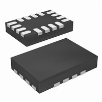
IC CTRLR VREG PWM DC/DC 16-TQFN
Manufacturer
Intersil
Datasheet
1.ISL62870HRUZ-T.pdf
(16 pages)
Specifications of ISL62870HRUZ-T
Pwm Type
Controller
Number Of Outputs
1
Frequency - Max
330kHz
Duty Cycle
100%
Voltage - Supply
3.3 V ~ 25 V
Buck
Yes
Boost
No
Flyback
No
Inverting
No
Doubler
No
Divider
No
Cuk
No
Isolated
No
Operating Temperature
-10°C ~ 100°C
Package / Case
16-UTQFN (16-µTQFN)
Frequency-max
330kHz
Lead Free Status / RoHS Status
Lead free / RoHS Compliant
Available stocks
Company
Part Number
Manufacturer
Quantity
Price
Company:

Part Number:
ISL62870HRUZ-T
Manufacturer:
M/A-COM
Quantity:
45
Part Number:
ISL62870HRUZ-T
Manufacturer:
INTERSIL
Quantity:
20 000


For example, if I
R
Resistor R
to sense the inductor current. To sense the inductor current
correctly not only in DC operation, but also during dynamic
operation, the R-C network time constant R
needs to match the inductor time constant L/DCR. The value
of C
For example, if L is 1.5µH, DCR is 4.5mΩ, and R
9kΩ, the choice of C
When an OCP fault is declared, the PGOOD pin will
pull-down to 35Ω and latch off the converter. The fault will
remain latched until the EN pin has been pulled below the
falling EN threshold voltage V
below the falling POR threshold voltage V
Overvoltage
The OVP fault detection circuit triggers after the FB pin
voltage is above the rising overvoltage threshold V
more than 2µs. For example, if the converter is programmed
to regulate 1.0V at the FB pin, that voltage would have to
rise above the typical V
than 2µs in order to trip the OVP fault latch. In numerical terms,
that would be 116% x 1.0V = 1.16V. When an OVP fault is
declared, the PGOOD pin will pull-down to 65Ω and latch-off
the converter. The OVP fault will remain latched until VCC
has decayed below the falling POR threshold voltage
V
pin below the falling EN threshold voltage V
Although the converter has latched-off in response to an OVP
fault, the LGATE gate-driver output will retain the ability to
toggle the low-side MOSFET on and off, in response to the
output voltage transversing the V
thresholds. The LGATE gate-driver will turn-on the low-side
MOSFET to discharge the output voltage, protecting the load.
The LGATE gate-driver will turn-off the low-side MOSFET
once the FB pin voltage is lower than the falling overvoltage
threshold V
threshold V
voltage falls below 102% x 1.0V = 1.02V, for more than 2µs,
the LGATE gate-driver will turn off the low-side MOSFET. If
the output voltage rises again, the LGATE driver will again
turn on the low-side MOSFET when the FB pin voltage is
above the rising overvoltage threshold V
2µs. By doing so, the IC protects the load when there is a
consistent overvoltage condition.
Undervoltage
The UVP fault detection circuit triggers after the FB pin
voltage is below the undervoltage threshold V
than 2µs. For example, if the converter is programmed to
regulate 1.0V at the FB pin, that voltage would have to fall
C
VCC_THF
OCSET
SEN
SEN
=
----------------------------------------- -
R
is then written as follows:
is = 20Ax4.5mΩ/10µA = 9kΩ.
OCSET
OCSET
. An OVP fault cannot be reset by pulling the EN
OVFTH
OVRTH
L
OC
⋅
and capacitor C
DCR
is typically 102%. That means if the FB pin
for more than 2µs. The falling overvoltage
is 20A and DCR is 4.5mΩ, the choice of
SEN
OVRTH
= 1.5µH/(9kΩx4.5mΩ) = 0.037µF.
ENTHF
8
threshold of 116% for more
OVRTH
SEN
or if VCC has decayed
form an R-C network
OVRTH
and V
VCC_THF
OCSET
ENTHF
UVTH
OVFTH
for more than
OCSET
OVRTH
.
C
for more
SEN
(EQ. 9)
is
for
ISL62870
below the typical V
in order to trip the UVP fault latch. In numerical terms, that
would be 84% x 1.0V = 0.84V. When a UVP fault is declared,
the PGOOD pin will pull-down to 95Ω and latch-off the
converter. The fault will remain latched until the EN pin has
been pulled below the falling EN threshold voltage V
or if VCC has decayed below the falling POR threshold
voltage V
Over-Temperature
When the temperature of the IC increases above the rising
threshold temperature T
that suspends the PWM, forcing the LGATE and UGATE
gate-driver outputs low. The status of the PGOOD pin does
not change nor does the converter latch-off. The PWM
remains suspended until the IC temperature falls below the
hysteresis temperature T
operation resumes. The OTP state can be reset if the EN pin
is pulled below the falling EN threshold voltage V
VCC has decayed below the falling POR threshold voltage
V
while the IC is in the OTP state. It is likely that the IC will
detect an UVP fault because in the absence of PWM, the
output voltage decays below the undervoltage threshold
V
Theory of Operation
The modulator features Intersil’s R
Regulator technology, a hybrid of fixed frequency PWM
control and variable frequency hysteretic control. The PWM
frequency is maintained at 300kHz under static continuous
conduction mode operation within the entire specified
envelope of input voltage, output voltage, and output load. If
the application should experience a rising load transient
and/or a falling line transient such that the output voltage
starts to fall, the modulator will extend the on-time and/or
reduce the off-time of the PWM pulse in progress.
Conversely, if the application should experience a falling
load transient and/or a rising line transient such that the
output voltage starts to rise, the modulator will truncate the
on-time and/or extend the off-time of the PWM pulse in
progress. The period and duty cycle of the ensuing PWM
pulses are optimized by the R
of the transient and work in concert with the error amplifier
V
transient has dissipated and the control loop has recovered,
the PWM frequency returns to the nominal static 300kHz.
Modulator
The R
analog representation of the output inductor ripple current.
The duty-cycle of V
current through a ripple capacitor C
C
measures the input voltage (V
VCC_THF
UVTH
ERR
R
is provided by a transconductance amplifier g
3
to maintain output voltage regulation. Once the
.
modulator synthesizes an AC signal V
VCC_THF
. All other protection circuits remain functional
.
UVTH
R
is the result of charge and discharge
OTRTH
OTHYS
threshold of 84% for more than 2µs
3
IN
, it will enter the OTP state
modulator for the remainder
, at which time normal PWM
) at the PHASE pin and
3
R
Robust-Ripple
. The current through
R
, which is an
ENTHF
August 14, 2008
m
that
ENTHF
FN6708.0
or if
Related parts for ISL62870HRUZ-T
Image
Part Number
Description
Manufacturer
Datasheet
Request
R

Part Number:
Description:
PWM DC/DC Voltage Regulator Controller
Manufacturer:
Intersil Corporation
Datasheet:
Part Number:
Description:
Intersil Corporation [CMOS Serial Controller Interface]
Manufacturer:
Intersil Corporation
Datasheet:
Part Number:
Description:
Manufacturer:
Intersil Corporation
Datasheet:
Part Number:
Description:
357-036-542-201 CARDEDGE 36POS DL .156 BLK LOPRO
Manufacturer:
Intersil Corporation
Datasheet:
Part Number:
Description:
1024-Word x 4-Bit LSI Static RAM
Manufacturer:
Intersil Corporation
Datasheet:
Part Number:
Description:
General Purpose NPN Transistor Arrays FN341.4
Manufacturer:
Intersil Corporation
Datasheet:
Part Number:
Description:
CMOS 16-Bit Microprocessor
Manufacturer:
Intersil Corporation
Datasheet:
Part Number:
Description:
Manufacturer:
Intersil Corporation
Datasheet:
Part Number:
Description:
Manufacturer:
Intersil Corporation
Datasheet:
Part Number:
Description:
Manufacturer:
Intersil Corporation
Datasheet:
Part Number:
Description:
Manufacturer:
Intersil Corporation
Datasheet:
Part Number:
Description:
CMOS 6-Bit Latch and Decoder Memory Interfaces
Manufacturer:
Intersil Corporation
Datasheet:
Part Number:
Description:
CA3046General Purpose NPN Transistor Arrays
Manufacturer:
Intersil Corporation
Datasheet:
Part Number:
Description:
Manufacturer:
Intersil Corporation
Datasheet:
Part Number:
Description:
TR909 DLC/FLC SLIC with Low Power Standby
Manufacturer:
Intersil Corporation
Datasheet: