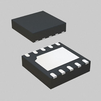
IR3624MTRPBF International Rectifier, IR3624MTRPBF Datasheet - Page 9

IR3624MTRPBF
Manufacturer Part Number
IR3624MTRPBF
Description
IC CTRLR PWM SYNC BUCK 10-MLPD
Manufacturer
International Rectifier
Datasheet
1.IR3624MPBF.pdf
(21 pages)
Specifications of IR3624MTRPBF
Package / Case
10-MLPD
Voltage - Supply
4.5 V ~ 14 V
Frequency-max
660kHz
Operating Temperature
-40°C ~ 125°C
Number Of Outputs
1
Duty Cycle
71%
Pwm Type
Voltage Mode
Buck
Yes
Boost
No
Flyback
No
Inverting
No
Doubler
No
Divider
No
Cuk
No
Isolated
No
Frequency
600kHz
Supply Voltage Range
4.5V To 14V
Digital Ic Case Style
MLPD
No. Of Pins
10
Operating Temperature Range
-40°C To +125°C
Termination Type
SMD
Input Voltage Primary Min
5V
Rohs Compliant
Yes
Filter Terminals
SMD
Control Mode
Voltage
Controller Type
PWM
Package
10-Lead MLPD
Circuit
Sync PWM Controller
Vcc (min)
4.0
Vcc (max)
14
Vout (min)
0.6
Vout (max)
Vcc * 0.71
Iout (a)
10
Switch Freq (khz)
Internal 600kHz
Pbf
PbF Option Available
Lead Free Status / RoHS Status
Lead free / RoHS Compliant
Other names
IR3624MPBFTR
Available stocks
Company
Part Number
Manufacturer
Quantity
Price
Part Number:
IR3624MTRPBF
Manufacturer:
IR
Quantity:
20 000
For a given start-up time, the soft-start capacitor
(nF) can be estimated as:
Soft-Start
The IR3624 has programmable soft-start to
control the output voltage rise and limit the inrush
current during start-up.
To
sequence initiates when Vcc and Vc rise above
their threshold and generate the Power On
Ready (POR) signal. The soft-start function
operates by sourcing current to charge an
external capacitor to about 3V.
Initially, the soft-start function clamps the output
of error amplifier by injecting a current (40uA)
into the Fb pin and generates a voltage about
0.96V (40ux24K) across the negative input of
error amplifier (see figure 5).
The magnitude of the injected current is inversely
proportional to the voltage at the soft-start pin. As
the soft-start voltage ramps up, the injected
current decreases linearly and so does the
voltage at negative input of error amplifier.
When the soft-start capacitor is around 1V, the
voltage at the positive input of the error amplifier
is approximately 0.6V.
The output of error amplifier will start increasing
and generating the first PWM signal. As the soft-
start capacitor voltage continues to go up, the
current flowing into the Fb pin will keep
decreasing.
The feedback voltage increases linearly as the
soft start voltage ramps up. When soft-start
voltage is around 2V the output voltage is
reached the steady state and the injected current
is zero.
Figure 6 shows the theoretical operational
waveforms during soft-start.
The output voltage start-up time is the time
period
increases from 1V to 2V.
The start-up time will be dependent on the size of
the external soft-start capacitor and can be
estimate by:
ensure
C
when
SS
20
≅
20
µA
correct
µ
∗
A
soft-start
T
C
*
start
ss
T
start
=
2
(
start-up,
ms
V
−
)
1
V
capacitor
--(
) 1
the
soft-start
voltage
Voltage at negative input
SS/SD
Comp
Voltage at Fb pin
Output of UVLO
Current flowing
0.6V
Fig. 6: Theoretical operation waveforms
Fig. 5: Soft-Start circuit for IR3624
Fb
of Error Amp
POR
into Fb pin
Soft-Start
20uA
Voltage
POR
≅ 0.96V
during soft-start
24K
24K
40uA
0V
0V
IR3624MPBF
3V
40uA
Error Amp
0uA
0.6V
0.6V
≅ 1V
≅ 2V
3V
9


