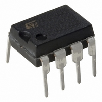
UC3845BN STMicroelectronics, UC3845BN Datasheet - Page 4

UC3845BN
Manufacturer Part Number
UC3845BN
Description
IC CTLR PWM HP CURR MODE 8-DIP
Manufacturer
STMicroelectronics
Datasheet
1.UC3845BD1013TR.pdf
(15 pages)
Specifications of UC3845BN
Pwm Type
Current Mode
Number Of Outputs
1
Frequency - Max
500kHz
Duty Cycle
50%
Voltage - Supply
8.2 V ~ 25 V
Buck
No
Boost
Yes
Flyback
Yes
Inverting
No
Doubler
No
Divider
No
Cuk
No
Isolated
Yes
Operating Temperature
0°C ~ 70°C
Package / Case
8-DIP (0.300", 7.62mm)
Frequency-max
500kHz
Duty Cycle (max)
50 %
Output Voltage
4.90 V to 5.10 V
Output Current
1000 mA (Max)
Mounting Style
Through Hole
Switching Frequency
500 KHz
Operating Supply Voltage
30 V
Maximum Operating Temperature
150 C
Fall Time
50 ns
Minimum Operating Temperature
- 40 C
Rise Time
50 ns
Synchronous Pin
No
Topology
Boost or Flyback
Input Voltage
15V
Frequency
250kHz
Power Dissipation Pd
1.25W
Supply Voltage Range
12V To 25V
Digital Ic Case Style
DIP
No. Of Pins
8
Rohs Compliant
Yes
For Use With
497-5863 - EVAL BOARD 2W 3PH SMPS BRKR ESBT
Lead Free Status / RoHS Status
Lead free / RoHS Compliant
Other names
STUC3845BN
Available stocks
Company
Part Number
Manufacturer
Quantity
Price
Company:
Part Number:
UC3845BN
Manufacturer:
MOT
Quantity:
5 510
Company:
Part Number:
UC3845BN
Manufacturer:
ST-MICROE
Quantity:
7 667
Part Number:
UC3845BN
Manufacturer:
ST
Quantity:
20 000
Company:
Part Number:
UC3845BNG
Manufacturer:
ON Semiconductor
Quantity:
5 700
Part Number:
UC3845BNG
Manufacturer:
ON/安森美
Quantity:
20 000
Notes : 1. Max package power dissipation limits must be respected; low duty cycle pulse techniques are used during test maintain T
UC2842B/3B/4B/5B - UC3842B/3B/4B/5B
ELECTRICAL CHARACTERISTICS (continued)
4/15
OUTPUT SECTION
UNDER-VOLTAGE LOCKOUT SECTION
PWM SECTION
TOTAL STANDBY CURRENT
Symbol
V
V
V
V
I
OLS
t
OH
t
I
OL
st
r
f
i
iz
2. These parameters, although guaranteed, are not 100% tested in production.
3. Parameter measured at trip point of latch with V
4. Gain defined as :
5. Adjust V
close to T
A =
Output Low Level
Output High Level
UVLO Saturation
Rise Time
Fall Time
Start Threshold
Min Operating Voltage
After Turn-on
Maximum Duty Cycle
Minimum Duty Cycle
Start-up Current
Operating Supply Current
Zener Voltage
V
V
i
above the start threshold before setting at 15 V.
PIN1
PIN3
amb
Parameter
as possible.
; 0 V
PIN3
0.8 V
I
I
I
T
T
X842B/4B
X843B/5B
X842B/4B
X843B/5B
X842B/3B
X844B/5B
V
V
V
I
VCC = 6V; I
I
SINK
SINK
SOURCE
SOURCE
i
j
j
i
i
PIN2
= 25mA
= 25 C C
= 25 C C
= 6.5V for UCX843B/45B
= 14V for UCX842B/44B
Test Conditions
= 20mA
= 200mA
= V
PIN2
= 20mA
= 200mA
PIN3
= 0.
SINK
L
L
= 0V
= 1nF (2)
= 1nF (2)
= 1mA
Min. Typ. Max. Min. Typ. Max.
7.8
7.0
13
12
15
94
47
30
9
UC284XB
13.5
13.5
0.1
1.6
0.1
8.4
7.6
0.3
0.3
50
50
16
10
96
48
12
36
150
150
100
0.4
2.2
1.1
9.0
8.2
0.5
0.5
17
11
50
17
0
14.5
7.8
8.5
7.0
13
12
94
47
30
UC384XB
13.5
13.5
1.6
0.1
0.1
8.4
7.6
0.3
0.3
50
50
16
10
96
48
12
36
17.5
11.5
150
150
100
0.4
2.2
1.1
9.0
8.2
0.5
0.5
50
17
0
j
Unit
as
mA
mA
mA
ns
ns
%
%
%
V
V
V
V
V
V
V
V
V
V


