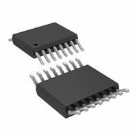
LT3574IMS#PBF Linear Technology, LT3574IMS#PBF Datasheet - Page 14

LT3574IMS#PBF
Manufacturer Part Number
LT3574IMS#PBF
Description
IC PWM FLYBCK ISO CM 16MSOP
Manufacturer
Linear Technology
Type
Flyback, Isolated, PWM - Current Moder
Datasheet
1.LT3574EMSPBF.pdf
(24 pages)
Specifications of LT3574IMS#PBF
Internal Switch(s)
Yes
Synchronous Rectifier
No
Number Of Outputs
1
Voltage - Output
Adj to 60V
Current - Output
650mA
Frequency - Switching
40kHz ~ 1MHz
Voltage - Input
3 ~ 40 V
Operating Temperature
-40°C ~ 125°C
Mounting Type
*
Package / Case
16-MSOP
Voltage - Supply
3 V ~ 40 V
Frequency-max
1MHz
Duty Cycle
52%
Pwm Type
Current Mode
Buck
No
Boost
No
Flyback
Yes
Inverting
No
Doubler
No
Divider
No
Cuk
No
Isolated
Yes
Lead Free Status / RoHS Status
Lead free / RoHS Compliant
Available stocks
Company
Part Number
Manufacturer
Quantity
Price
LT3574
Setting the Current Limit Resistor
The maximum current limit can be set by placing a resistor
between the R
flexibility in picking standard off-the-shelf transformers that
may be rated for less current than the LT3574’s internal
power switch current limit. If the maximum current limit
is needed, use a 10k resistor. For lower current limits, the
following equation sets the approximate current limit:
The Switch Current Limit vs R
formance Characteristics section depicts a more accurate
current limit.
Undervoltage Lockout (UVLO)
The SHDN/UVLO pin is connected to a resistive voltage
divider connected to V
threshold on the SHDN/UVLO pin for V
To introduce hysteresis, the LT3574 draws 2.5µA from the
SHDN/UVLO pin when the pin is below 1.22V. The hysteresis
is therefore user-adjustable and depends on the value of
R1. The UVLO threshold for V
The UVLO threshold for V
applications inForMation
R
V
V
IN UVLO RISING
IN UVLO FALLING
ILIM
(
(
=
65 10 0 9
,
,
ILIM
•
3
)
pin and ground. This provides some
( .
)
=
IN
=
1 22
as shown in Figure 8. The voltage
1 22
.
A I
.
IN
−
V R
falling is:
LIM
V R
ILIM
IN
• (
R
• (
R
2
rising is:
)
2
1
+
plot in the Typical Per-
1
+
10
+
R
R
2
k
IN
)
2
)
Figure 8. Undervoltage Lockout (UVLO)
+
rising is 1.22V.
2 5
LT3574
SHDN/UVLO
.
µA R
GND
•
1
V
IN
R1
R2
To implement external run/stop control, connect a small
NMOS to the UVLO pin, as shown in Figure 8. Turning the
NMOS on grounds the UVLO pin and prevents the LT3574
from operating, and the part will draw less than a 1µA of
quiescent current.
Minimum Load Requirement
The LT3574 obtains output voltage information through
the transformer while the secondary winding is conducting
current. During this time, the output voltage (multiplied
times the turns ratio) is presented to the primary side of
the transformer. The LT3574 uses this reflected signal to
regulate the output voltage. This means that the LT3574
must turn on every so often to sample the output voltage,
which delivers a small amount of energy to the output.
This sampling places a minimum load requirement on the
output of 1% to 2% of the maximum load.
BIAS Pin Considerations
For applications with an input voltage less than 15V, the
BIAS pin is typically connected directly to the V
input voltages greater than 15V, it is preferred to leave the
BIAS pin separate from the V
BIAS pin is regulated with an internal LDO to a voltage of
3V. By keeping the BIAS pin separate from the input voltage
at high input voltages, the physical size of the capacitors
can be minimized (the BIAS pin can then use a 6.3V or
10V rated capacitor).
3574 F08
RUN/STOP
CONTROL
(OPTIONAL)
IN
pin. In this condition, the
IN
pin. For
3574f


