MIC22602YML TR Micrel Inc, MIC22602YML TR Datasheet - Page 13
MIC22602YML TR
Manufacturer Part Number
MIC22602YML TR
Description
ID BUCK SYNC ADJ 6A 24MLF
Manufacturer
Micrel Inc
Type
Step-Down (Buck), PWM - Voltage Moder
Datasheet
1.MIC22602YML_TR.pdf
(24 pages)
Specifications of MIC22602YML TR
Internal Switch(s)
Yes
Synchronous Rectifier
Yes
Number Of Outputs
1
Voltage - Output
Adj to 0.7V
Current - Output
6A
Frequency - Switching
1MHz
Voltage - Input
2.6 ~ 5.5 V
Operating Temperature
-40°C ~ 125°C
Mounting Type
Surface Mount
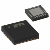
Package / Case
24-MLF®, QFN
Voltage - Supply
2.6 V ~ 5.5 V
Frequency-max
1.2MHz
Duty Cycle
100%
Pwm Type
Voltage Mode
Buck
Yes
Boost
No
Flyback
No
Inverting
No
Doubler
No
Divider
No
Cuk
No
Isolated
No
Lead Free Status / RoHS Status
Lead free / RoHS Compliant
Other names
576-3645-2
MIC22602YML TR
MIC22602YMLTR
MIC22602YML TR
MIC22602YMLTR


Feedback
The MIC22602 provides a feedback pin to adjust the
output voltage to the desired level. This pin connects
internally to an error amplifier. The error amplifier then
compares the voltage at the feedback to the internal
0.7V reference voltage and adjusts the output voltage to
maintain regulation. The resistor divider network for a
desired V
where V
voltage. A 10kΩ or lower resistor value from the output
to the feedback is recommended since large feedback
resistor values increase the impedance at the feedback
pin, making the feedback node more susceptible to
noise pick-up. A small capacitor (50pF – 100pF) across
the lower resistor can reduce noise pick-up by providing
a low impedance path to ground.
PWM Operation
The MIC22602 is a voltage mode, pulse width
modulation (PWM) controller. By controlling the duty
cycle, a regulated DC output voltage is achieved. As
load or supply voltage changes, so does the duty cycle
to maintain a constant output voltage. In cases where
the input supply runs into a dropout condition, the
MIC22602 will run at 100% duty cycle.
The MIC22602 provides constant switching at 1MHz with
synchronous internal MOSFETs. The internal MOSFETs
include a high-side P-Channel MOSFET from the input
supply to the switch pin and an N-Channel MOSFET
from the switch pin-to-ground. Since the low-side N-
Channel MOSFET provides the current during the off
cycle, very low power is dissipated during the off period.
PWM control provides fixed frequency operation. By
maintaining a constant switching frequency, predictable
fundamental and harmonic frequencies are achieved.
Sequencing and tracking
The MIC22602 provides additional pins to provide
up/down
connecting multiple voltage regulators together.
Micrel, Inc.
October 2009
R
REF
OUT
2
sequencing
=
is given by:
is 0.7V and V
⎛
⎜ ⎜
⎝
V
V
OUT
REF
R
1
−
1
⎞
⎟ ⎟
⎠
and
OUT
tracking
is the desired output
capability
for
13
EN/DLY pin
The EN pin contains a trimmed, 1µA current source
which can be used with a capacitor to implement a fixed
desired delay in some sequenced power systems. The
threshold level for power on is 1.24V with a hysteresis of
20mV.
DELAY Pin
The DELAY pin also has a 1µA trimmed current source
and a 1µA current sink which acts with an external
capacitor to delay the operation of the Power On Reset
(POR) output. This can be used also in sequencing
outputs in a sequenced system, but with the addition of a
conditional delay between supplies; allowing a first up,
last down power sequence.
After EN is driven high, V
determined by RC capacitor). As the FB voltage goes
above 90% of its nominal set voltage, DELAY begins to
rise as the 1µA source charges the external capacitor.
When the threshold of 1.24V is crossed, POR is
asserted high and DELAY continues to charge to a
voltage SVIN. When FB falls below 90% of nominal,
POR is asserted low immediately. However, if EN is
driven low, POR will fall immediately to the low state and
DELAY will begin to fall as the external capacitor is
discharged by the 1µA current sink. When the threshold
of (V
voltage clamp V
rate determined by the RC capacitor. As the voltage
change in both cases is 1.24V, both rising and falling
delays are matched at
RC pin
The RC pin provides a trimmed 1µA current source/sink
similar to the DELAY Pin for accurate ramp up (soft
start) and ramp down control. This allows the MIC22602
to be used in systems requiring voltage tracking or ratio-
metric voltage tracking at startup.
There are two ways of using the RC pin:
In the first case, driving RC with a voltage from 0V to
V
of the nominal set voltage.
In the second case, the external capacitor sets the ramp
up and ramp down time of the output voltage. The time
is given by
from 0 to 100% nominal output voltage.
The RC pin cannot be left floating. Use a minimum
capacitor value of 470pF or larger.
REF
1. Externally driven from a voltage source
2. Externally attached capacitor sets output ramp
programs the output voltage between 0 and 100%
TP
+1.24V)-1.24V is crossed (V
up/down rate
T
RAMP
TP
≈ 0.9V ), V
=
0
1
T
7 .
×
POR
10
⋅
C
−
RC
6
=
OUT
. 1
OUT
where T
1
24
will start to rise (rate
×
will begin to fall at a
10
⋅
C
−
TP
DLY
6
M9999-102809-A
RAMP
is the internal
MIC22602
is the time
Related parts for MIC22602YML TR
Image
Part Number
Description
Manufacturer
Datasheet
Request
R

Part Number:
Description:
Manufacturer:
Micrel Inc
Datasheet:
Part Number:
Description:
Manufacturer:
Micrel Inc
Datasheet:
Part Number:
Description:
Manufacturer:
Micrel Inc
Datasheet:
Part Number:
Description:
Manufacturer:
Micrel Inc
Datasheet:
Part Number:
Description:
Manufacturer:
Micrel Inc
Datasheet:
Part Number:
Description:
Manufacturer:
Micrel Inc
Datasheet:
Part Number:
Description:
Manufacturer:
Micrel Inc
Datasheet:
Part Number:
Description:
Manufacturer:
Micrel Inc
Datasheet:
Part Number:
Description:
Manufacturer:
Micrel Inc
Datasheet:
Part Number:
Description:
Manufacturer:
Micrel Inc
Datasheet:
Part Number:
Description:
Manufacturer:
Micrel Inc
Datasheet:
Part Number:
Description:
Manufacturer:
Micrel Inc
Datasheet:
Part Number:
Description:
Manufacturer:
Micrel Inc
Datasheet:
Part Number:
Description:
Manufacturer:
Micrel Inc
Datasheet: