MIC22602YML TR Micrel Inc, MIC22602YML TR Datasheet - Page 10
MIC22602YML TR
Manufacturer Part Number
MIC22602YML TR
Description
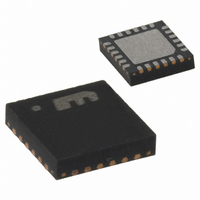
ID BUCK SYNC ADJ 6A 24MLF
Manufacturer
Micrel Inc
Type
Step-Down (Buck), PWM - Voltage Moder
Datasheet
1.MIC22602YML_TR.pdf
(24 pages)
Specifications of MIC22602YML TR
Internal Switch(s)
Yes
Synchronous Rectifier
Yes
Number Of Outputs
1
Voltage - Output
Adj to 0.7V
Current - Output
6A
Frequency - Switching
1MHz
Voltage - Input
2.6 ~ 5.5 V
Operating Temperature
-40°C ~ 125°C
Mounting Type
Surface Mount
Package / Case
24-MLF®, QFN
Voltage - Supply
2.6 V ~ 5.5 V
Frequency-max
1.2MHz
Duty Cycle
100%
Pwm Type
Voltage Mode
Buck
Yes
Boost
No
Flyback
No
Inverting
No
Doubler
No
Divider
No
Cuk
No
Isolated
No
Lead Free Status / RoHS Status
Lead free / RoHS Compliant
Other names
576-3645-2
MIC22602YML TR
MIC22602YMLTR
MIC22602YML TR
MIC22602YMLTR


Functional Description
PVIN, SVIN
PVIN is the input supply to the internal 30mΩ P-Channel
Power MOSFET. This should be connected externally to
the SVIN pin. The supply voltage range is from 2.6V to
5.5V. A 22µF ceramic is recommended for bypassing
each PVIN supply.
EN/DLY
This pin is internally fed with a 1µA current source from
VIN. A delayed turn on is implemented by adding a
capacitor to this pin. The delay is proportional to the
capacitor value. The internal circuits are held off until
EN/DLY reaches the enable threshold of 1.24V.
RC
RC allows the slew rate of the output voltage to be
programmed by the addition of a capacitor from RC to
ground. RC is internally fed with a 1µA current source
and VOUT slew rate is proportional to the capacitor and
the 1µA source. The RC pin cannot be left floating. Use
a minimum capacitor value of 470pF or larger.
DELAY
Adding a capacitor to this pin allows the delay of the
POR signal.
When VOUT reaches 90% of its nominal voltage, the
DELAY pin current source (1µA) starts to charge the
external capacitor. At 1.24V, POR is asserted high.
COMP
The MIC22602 uses an internal compensation network
containing a fixed frequency zero (phase lead response)
and pole (phase lag response) which allows the external
compensation network to be much simplified for stability.
The addition of a single capacitor and resistor will add
the necessary pole and zero for voltage mode loop
stability using low value, low ESR ceramic capacitors.
Micrel, Inc.
October 2009
10
FB
The feedback pin provides the control path to control the
output. A resistor divider connecting the feedback to the
output is used to adjust the desired output voltage. Refer
to the feedback section in the “Applications Information”
for more detail.
POR
This is an open drain output. A 47.5k resistor can be
used for a pull up to this pin. POR is asserted high when
output voltage reaches 90% of nominal set voltage and
after the delay set by C
without delay when enable is set low or when the output
goes below the -10% threshold. For a Power Good (PG)
function, the delay can be set to a minimum. This can be
done by removing the DELAY capacitor.
SW
This is the connection to the drain of the internal P-
Channel MOSFET and drain of the N-Channel MOSFET.
This is a high frequency high power connection;
therefore traces should be kept as short and as wide as
practical.
SGND
Internal signal ground for all low power sections.
PGND
Internal ground connection to the source of the internal
N-Channel MOSFETs.
DELAY
. POR is asserted low
M9999-102809-A
MIC22602
Related parts for MIC22602YML TR
Image
Part Number
Description
Manufacturer
Datasheet
Request
R

Part Number:
Description:
Manufacturer:
Micrel Inc
Datasheet:
Part Number:
Description:
Manufacturer:
Micrel Inc
Datasheet:
Part Number:
Description:
Manufacturer:
Micrel Inc
Datasheet:
Part Number:
Description:
Manufacturer:
Micrel Inc
Datasheet:
Part Number:
Description:
Manufacturer:
Micrel Inc
Datasheet:
Part Number:
Description:
Manufacturer:
Micrel Inc
Datasheet:
Part Number:
Description:
Manufacturer:
Micrel Inc
Datasheet:
Part Number:
Description:
Manufacturer:
Micrel Inc
Datasheet:
Part Number:
Description:
Manufacturer:
Micrel Inc
Datasheet:
Part Number:
Description:
Manufacturer:
Micrel Inc
Datasheet:
Part Number:
Description:
Manufacturer:
Micrel Inc
Datasheet:
Part Number:
Description:
Manufacturer:
Micrel Inc
Datasheet:
Part Number:
Description:
Manufacturer:
Micrel Inc
Datasheet:
Part Number:
Description:
Manufacturer:
Micrel Inc
Datasheet: