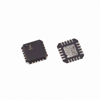
ISL6420IRZ Intersil, ISL6420IRZ Datasheet - Page 14

ISL6420IRZ
Manufacturer Part Number
ISL6420IRZ
Description
IC CTRLR PWM BUCK SYNC SGL 20QFN
Manufacturer
Intersil
Datasheet
1.ISL6420IRZ.pdf
(19 pages)
Specifications of ISL6420IRZ
Pwm Type
Voltage Mode
Number Of Outputs
1
Frequency - Max
1.4MHz
Duty Cycle
100%
Voltage - Supply
4.5 V ~ 16 V
Buck
Yes
Boost
No
Flyback
No
Inverting
No
Doubler
No
Divider
No
Cuk
No
Isolated
No
Operating Temperature
-40°C ~ 85°C
Package / Case
20-VQFN Exposed Pad, 20-HVQFN, 20-SQFN, 20-DHVQFN
Frequency-max
1.4MHz
Peak Reflow Compatible (260 C)
Yes
Rohs Compliant
Yes
Lead Free Status / RoHS Status
Lead free / RoHS Compliant
Available stocks
Company
Part Number
Manufacturer
Quantity
Price
Company:
Part Number:
ISL6420IRZ
Manufacturer:
Intersil
Quantity:
135
Company:
Part Number:
ISL6420IRZ
Manufacturer:
Intersil
Quantity:
150
Company:
Part Number:
ISL6420IRZ-TK
Manufacturer:
INTERSIL
Quantity:
4 823
capacitor to 2.5V. The capacitor will be quickly discharged
before PGOOD goes high. The programmable delay can be
used to sequence multiple converters or as a LOW-true
reset signal.
If the voltage on the FB pin exceeds ±10% of the reference,
then PGOOD will go low after 3µs of noise filtering.
Over-Temperature Protection
The IC is protected against over temperature conditions.
When the junction temperature exceeds +150°C, the PWM
shuts off. Normal operation is resumed when the junction
temperature is cooled down to +130°C.
Shutdown
When ENSS pin is below 1V, the regulator is disabled with
the PWM output drivers tri-stated. When disabled, the IC
power will be reduced.
Under-Voltage
If the voltage on the FB pin is less than 15% of the reference
voltage for 8 consecutive PWM cycles, then the circuit enters
into soft-start hiccup mode. This mode is identical to the
overcurrent hiccup mode.
Overvoltage Protection
If the voltage on the FB pin exceeds the reference voltage by
15%, the lower gate driver is turned on continuously to
discharge the output voltage. If the overvoltage condition
continues for 32 consecutive PWM cycles, then the chip is
turned off with the gate drivers tri-stated. The voltage on the
FB pin will fall and reach the 15% undervoltage threshold.
After 8 clock cycles, the chip will enter soft-start hiccup
mode. This mode is identical to the overcurrent hiccup
mode.
FIGURE 12. PGOOD DELAY
14
ISL6420
Application Guidelines
Layout Considerations
As in any high frequency switching converter, layout is very
important. Switching current from one power device to
another can generate voltage transients across the
impedances of the interconnecting bond wires and circuit
traces. These interconnecting impedances should be
minimized by using wide, short printed circuit traces. The
critical components should be located as close together as
possible using ground plane construction or single point
grounding.
Figure 12 shows the critical power components of the
converter. To minimize the voltage overshoot the
interconnecting wires indicated by heavy lines should be part
of ground or power plane in a printed circuit board. The
components shown in Figure 12 should be located as close
together as possible. Please note that the capacitors C
and C
Locate the ISL6420 within 3 inches of the MOSFETs, Q1 and
Q2. The circuit traces for the MOSFETs’ gate and source
connections from the ISL6420 must be sized to handle up to
1A peak current.
Figure 13 shows the circuit traces that require additional
layout consideration. Use single point and ground plane
construction for the circuits shown. Minimize any leakage
current paths on the ENSS PIN and locate the capacitor, C
close to the ENSS pin because the internal current source is
only 30µA. Provide local V
GND pins. Locate the capacitor, C
to the BOOT and PHASE pins.
Feedback Compensation
Figure 14 highlights the voltage-mode control loop for a
synchronous-rectified buck converter. The output voltage
(Vout) is regulated to the Reference voltage level. The error
amplifier (Error Amp) output (V
FIGURE 13. PRINTED CIRCUIT BOARD POWER AND
ISL6420
O
each represent numerous physical capacitors.
UGATE
PHASE
LGATE
GND
GROUND PLANES OR ISLANDS
CC
V
Q2
Q1
RETURN
IN
decoupling between VCC and
E/A
D2
BOOT
) is compared with the
C
as close as practical
IN
L
O
C
O
February 13, 2008
V
OUT
FN9151.5
IN
ss


