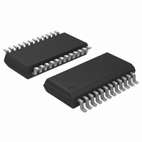
ADT7476AARQZ-REEL ON Semiconductor, ADT7476AARQZ-REEL Datasheet - Page 33

ADT7476AARQZ-REEL
Manufacturer Part Number
ADT7476AARQZ-REEL
Description
IC REMOTE THERMAL CTRLR 24-QSOP
Manufacturer
ON Semiconductor
Series
dBCool®r
Datasheet
1.ADT7476AARQZ.pdf
(67 pages)
Specifications of ADT7476AARQZ-REEL
Function
Fan Control, Temp Monitor
Topology
ADC, Comparator, Fan Speed Counter, Multiplexer, Register Bank
Sensor Type
External & Internal
Sensing Temperature
-40°C ~ 125°C, External Sensor
Output Type
SMBus™
Output Alarm
No
Output Fan
Yes
Voltage - Supply
3 V ~ 3.6 V
Operating Temperature
-40°C ~ 125°C
Mounting Type
Surface Mount
Package / Case
24-QSOP
Lead Free Status / RoHS Status
Lead free / RoHS Compliant
Step 1—Hardware Configuration
control capabilities should be addressed early in the design
stages. Decisions about how these capabilities are used
should involve the system thermal/mechanical engineer.
Ask the following questions:
•
•
•
•
reconfigured to suit different system requirements and
physical layouts. These multifunction pins are software
programmable.
During system design, the motherboard sensing and
The ADT7476A offers multifunctional pins that can be
PWM2 or SMBALERT?
TACH4 fan speed measurement or overtemperature
THERM function?
2.5 V voltage monitoring or overtemperature THERM
function?
12 V voltage monitoring or VID5 input?
1. What ADT7476A functionality is used?
AMBIENT TEMP
REMOTE 1 =
REMOTE 2 =
VRM TEMP
CPU TEMP
LOCAL =
THERMAL CALIBRATION
THERMAL CALIBRATION
THERMAL CALIBRATION
T
T
T
MIN
MIN
MIN
Figure 48. Hardware Configuration Example
T
T
T
RANGE
RANGE
RANGE
100%
100%
100%
0%
0%
0%
MUX
http://onsemi.com
33
PWM
PWM
PWM
MIN
MIN
MIN
measurement channels to particular system thermal zones.
For example, locating the ADT7476A close to the VRM
controller circuitry allows the VRM temperature to be
monitored using the local temperature channel.
This influences the assignment of the temperature
CONFIG
CONFIG
CONFIG
TACHOMETER 1
MEASUREMENT
TACHOMETER 2
MEASUREMENT
TACHOMETER 3
MEASUREMENT
2. How many fans are supported in system, three or
3. Is the CPU fan to be controlled using the
4. Where will the ADT7476A be physically located
PWM
PWM
PWM
GENERATOR
GENERATOR
GENERATOR
four? This influences the choice of whether to use
the TACH4 pin or to reconfigure it for the
THERM function.
ADT7476A, or will the CPU fan run at full speed
100% of the time?
in the system?
If run at 100%, this frees up a PWM output, but the
system is louder.
AND 4
PWM
PWM
PWM
ENHANCEMENT)
ENHANCEMENT)
ENHANCEMENT)
(ACOUSTIC
(ACOUSTIC
(ACOUSTIC
CONTROL
CONTROL
CONTROL
RAMP
RAMP
RAMP
PWM1
TACH1
PWM2
TACH2
PWM3
TACH3
FRONT CHASSIS
REAR CHASSIS
CPU FAN SINK


