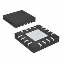
MAX6639ATE+ Maxim Integrated Products, MAX6639ATE+ Datasheet - Page 5

MAX6639ATE+
Manufacturer Part Number
MAX6639ATE+
Description
IC TEMP MONITOR 2CH 16-TQFN
Manufacturer
Maxim Integrated Products
Datasheet
1.MAX6639AEE.pdf
(22 pages)
Specifications of MAX6639ATE+
Function
Fan Control, Temp Monitor
Topology
ADC, PWM Generator, Tach Counter
Sensor Type
External & Internal
Sensing Temperature
0°C ~ 150°C, External Sensor
Output Type
I²C™/SMBus™
Output Alarm
Yes
Output Fan
Yes
Voltage - Supply
3 V ~ 3.6 V
Operating Temperature
-40°C ~ 125°C
Mounting Type
Surface Mount
Package / Case
16-TQFN Exposed Pad
Lead Free Status / RoHS Status
Lead free / RoHS Compliant
(V
T Q FN - EP
CC
1, 15
2, 16
8, 10
11
12
13
14
—
3
4
5
6
7
9
= 3.3V, T
PIN
QSOP
9, 12
3, 1
4, 2
A
10
11
13
14
16
15
—
2-Channel Temperature Monitor with Dual,
5
6
7
8
= +25°C.)
35
34
33
32
31
30
_______________________________________________________________________________________
-40
FANFAIL Active-Low, Open-Drain, Fan-Failure Output. Open circuit when V
TACH2,
THERM
PWM2,
TACH1
ALERT
NAME
PWM1
DXP1,
DXP2
GND
DXN
ADD
SDA
V
SCL
OT
EP
CC
Automatic, PWM Fan-Speed Controller
-15
vs. DIE TEMPERATURE
PWMOUT FREQUENCY
10
TEMPERATURE (°C)
Open-Drain Output to Power-Transistor Driving Fan. Connect to the gate of a MOSFET or base of a
bipolar transistor. PWM_ requires a pullup resistor. The pullup resistor can be connected to a
supply voltage as high as 13.5V, regardless of the MAX6639’s supply voltage.
Tachometer Inputs. Connect to the tachometer output of the fan. TACH_ requires a pullup resistor.
The pullup resistor can be connected to a supply voltage as high as 13.5V, regardless of the
MAX6639’s supply voltage.
Active-Low, Open-Drain Thermal Alarm Output. Typically used for clock throttling. Open circuit
when V
Active-Low, Open-Drain Overtemperature Output. Typically used for system shutdown or clock
throttling. Can be pulled up to 5.5V regardless of V
Power-Supply Input. 3.3V nominal. Bypass V
Ground. Connect to a clean ground reference.
C om b i ned C ur r ent S our ce and A/D P osi ti ve Inp ut for Rem ote D i od e. C onnect to anod e of r em ote-
d i od e- connected tem p er atur e- sensi ng tr ansi stor . D o not l eave unconnected ; connect to D X N i f no
r em ote d i od e i s used . P l ace a 2200p F cap aci tor b etw een D X P _ and D X N for noi se fi l ter i ng .
Rem ote D i od e C ur r ent S i nk Inp ut. C onnect C athod e of the Rem ote- D i od e- C onnected Tr ansi stor to D X N
Address Input. Sets device slave address. Connect to GND, V
three unique addresses. See Table 1.
Active-Low, Open-Drain SMBus Alert Output
SMBus Serial-Clock Input. Can be pulled up to 5.5V regardless of V
SMBus Serial-Data Input/Output, Open Drain. Can be pulled up to 5.5V regardless of V
circuit when V
Exposed Pad (TQFN package only). Internally connected to GND. Connect EP to a large PCB pad
for optimum performance and enhanced thermal dissipation. Not intended as an electrical
connection point.
35
CC
60
= 0.
85
CC
Typical Operating Characteristics (continued)
= 0.
110
FUNCTION
CC
35
34
33
32
31
30
to GND with a 0.1µF capacitor.
3.0
CC
. Open circuit when V
3.5
PWMOUT FREQUENCY
vs. SUPPLY VOLTAGE
SUPPLY VOLTAGE (V)
4.0
CC
, or leave unconnected to give
CC
CC
4.5
= 0.
. Open circuit when V
Pin Description
CC
5.0
= 0.
5.5
CC
. Open
CC
=
5


