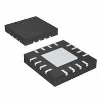
MAX6639ATE+ Maxim Integrated Products, MAX6639ATE+ Datasheet - Page 15

MAX6639ATE+
Manufacturer Part Number
MAX6639ATE+
Description
IC TEMP MONITOR 2CH 16-TQFN
Manufacturer
Maxim Integrated Products
Datasheet
1.MAX6639AEE.pdf
(22 pages)
Specifications of MAX6639ATE+
Function
Fan Control, Temp Monitor
Topology
ADC, PWM Generator, Tach Counter
Sensor Type
External & Internal
Sensing Temperature
0°C ~ 150°C, External Sensor
Output Type
I²C™/SMBus™
Output Alarm
Yes
Output Fan
Yes
Voltage - Supply
3 V ~ 3.6 V
Operating Temperature
-40°C ~ 125°C
Mounting Type
Surface Mount
Package / Case
16-TQFN Exposed Pad
Lead Free Status / RoHS Status
Lead free / RoHS Compliant
The following registers apply to the automatic RPM con-
trol mode:
• D[7:4]: Fan RPM (Tachometer) Step-Size A.
• D[3:2]: Temperature Step Size. Selects the temper-
• D1: PWM Output Polarity. PWM output is low at
• D0: Minimum Speed. Selects the value of the mini-
The following registers select the tachometer step sizes
and number of steps for step-size A to step-size B
slope changes (see Figure 1):
• D[7:4]: RPM (Tachometer) Step Size B. Selects
• D[3:0]: Selects the number of temperature/tachome-
The following registers control fan spin-up, PWM output
frequency, pulse stretching, and THERM to fan full-
speed enable:
Table 8. Temperature Step Size
REGISTER 11h
Selects the number of tachometer counts the target
value decreases for each temperature step increase
above the fan-start temperature. Value = n + 1 (1
through 16) where n is the value of D[7:4].
ature increment for fan control. For each temperature
step increase, the target tachometer count decreas-
es by the value selected by D[7:4] (Table 8).
100% duty cycle when this bit is set to zero. PWM
output is high at 100% duty cycle when this bit is set
to 1.
mum fan speed (when temperature is below the fan-
start temperature in the automatic RPM control
mode). Set to zero for 0% fan drive. Set to 1 to deter-
mine the minimum fan speed by the tachometer
count value in registers 22h and 23h (fan maximum
TACH).
number of tachometer counts the target value
decreases for each temperature step increase after
the number of steps selected by D[3:0]. Value = n +
1 (1 through 16) where n is the value of D[7:4].
ter steps above the fan-start temperature at which
step-size B begins.
OR 15h
Fan 1 and Fan 2 Configuration 3 (13h and 17h)
00
01
10
11
Fan 1 and 2 Configuration 2b (12h and 16h)
Fan 1 and 2 Configuration 2a (11h and 15h)
2-Channel Temperature Monitor with Dual,
______________________________________________________________________________________
FAN CONTROL TEMPERATURE
Automatic, PWM Fan-Speed Controller
STEP SIZE (°C)
1
2
4
8
• D7: Fan Spin-Up Disable. Set to zero to enable fan
• D6: THERM to Full-Speed Enable. When this bit is
• D5: Disable Pulse Stretching. Pulse stretching is
• D[1:0]: PWM Output Frequency. These bits control
These registers have the latest tachometer measure-
ment of the corresponding channel. This is inversely
proportional to the fan’s speed. The fan RPM range
should be set so this count falls in the 30 to 160 range
for normal fan operation.
D[7:0]: This sets the starting tachometer count for the
fan in automatic RPM mode. Depending on the setting
of the minimum duty-cycle bit, the tachometer count
has this value either at all temperatures below the fan-
start temperature or the count is zero below the fan-
start temperature and has this value when the fan-start
temperature is reached. These registers are the target
tach count when in manual RPM mode.
Table 9. Fan PWM Frequency
13h AND 16h
REGISTERS
spin-up. Whenever the fan starts up from zero drive,
it is driven with 100% duty cycle for 2s to ensure that
it starts. Set to 1 to disable the spin-up function.
1, THERM going low (either by being pulled low
externally or by the measured temperature exceed-
ing the THERM limit) forces the fan to full speed. In
all modes, this happens at the rate determined by
the rate-of-change selection. When THERM is
deasserted (even if the fan has not reached full
speed), the speed falls at the selected rate-of-
change to the target speed.
enabled when this bit is set to zero. When modulat-
ing the fan’s power supply with the PWM signal, the
PWM pulses are periodically stretched to keep the
tachometer signal available for one full revolution.
Setting this bit to 1 disables pulse stretching. The
MAX6639 still measures the fan speed but does not
stretch the pulses for measurements, so the fan’s
power supply must not be pulse modulated.
the PWM output frequency as shown in Table 9.
00
01
10
11
Fan Start Tach Count/Target Tach Count
Fan Tach Count 1 and 2 (20h and 21h)
LOW-FREQUENCY
(Hz) REGISTER
04h D3 = 0
33.33
100
20
50
HIGH-FREQUENCY
(kHz) REGISTER
04h D3 = 1
(22h and 23h)
8.33
12.5
25
5
15


