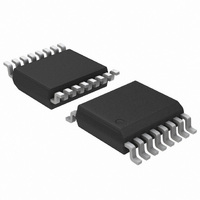
ADT7473ARQZ-1RL ON Semiconductor, ADT7473ARQZ-1RL Datasheet - Page 39

ADT7473ARQZ-1RL
Manufacturer Part Number
ADT7473ARQZ-1RL
Description
IC REMOTE THERMAL CTLR 16QSOP
Manufacturer
ON Semiconductor
Series
dBCool®r
Datasheet
1.ADT7473ARQZ-1RL.pdf
(74 pages)
Specifications of ADT7473ARQZ-1RL
Function
Fan Control, Temp Monitor
Topology
ADC, Comparator, Fan Speed Counter, Multiplexer, Register Bank
Sensor Type
External & Internal
Sensing Temperature
-40°C ~ 125°C, External Sensor
Output Type
SMBus™
Output Alarm
No
Output Fan
Yes
Voltage - Supply
3 V ~ 3.6 V
Operating Temperature
-40°C ~ 125°C
Mounting Type
Surface Mount
Package / Case
16-QSOP
Full Temp Accuracy
+/- 0.5 C
Digital Output - Bus Interface
Serial (3-Wire, 4-Wire)
Maximum Operating Temperature
+ 125 C
Minimum Operating Temperature
- 40 C
Lead Free Status / RoHS Status
Lead free / RoHS Compliant
Available stocks
Company
Part Number
Manufacturer
Quantity
Price
Company:
Part Number:
ADT7473ARQZ-1RL
Manufacturer:
ON Semiconductor
Quantity:
1 750
Part Number:
ADT7473ARQZ-1RL
Manufacturer:
ON/安森美
Quantity:
20 000
Example 4
40°C, and PWM
T
T
T
T
Selecting a T
channel: Remote 1, local, and Remote 2. Bits [7:4]
(T
T
Summary of T
temperature at which the fan reaches full speed can be
calculated by:
PWM duty cycle.
T
PWM duty cycle to temperature slope. The effective
T
using Equation 6.
where (Max DC − Min DC) x T
T
T
Table 13. Selecting a T
MAX
MAX
MAX
MAX
RANGE
1. Register 0x5F configures Remote 1 T
RANGE
RANGE
MAX
RANGE
Calculate T
The T
When using the automatic fan control function, the
Equation 1 holds true only when PWM
Increasing or decreasing PWM
RANGE
configures local T
T
Bits [7:4] (Note 1)
RANGE
+ T
= T
= 30°C + (100% − 50%) x 40°C/170
= 30°C + (255 − 128) x 40°C/170
= 60°C (effective T
RANGE
, although the fan control still follows the same
value for each temperature channel.
value.
) of Register 0x5F to Register 0x61 define the
for different PWM
MIN
MIN
0000
0001
0010
0100
0101
1000
1001
1010
.
0011
0110
0111
1011
1100
1101
1110
1111
RANGE
) Max DC * Min DC
MAX
+ (Max DC − Min DC) x T
RANGE
value can be selected for each temperature
T
MIN
MAX
, given that T
RANGE
Slope
= 50% duty cycle = 128 (decimal).
Function
+ T
RANGE
; Register 0x61 configures Remote 2
RANGE
MIN
MIN
) T
Value
RANGE
MIN
MIN
values can be calculated
= 30°C)
TRANGE
T
changes the effective
RANGE
32 (default)
= 30°C, T
RANGE
/170 is the effective
MIN
T
13.33
26.67
53.33
3.33
6.67
2.5
TRANGE
RANGE
10
16
20
40
80
2
4
5
8
; Register 0x60
is equal to 33%
(5C)
RANGE
/170
(eq. 5)
170
(eq. 6)
http://onsemi.com
=
39
Figure 59 shows PWM duty cycle vs. temperature for each
T
setting affects fan speed vs. temperature. As indicated by the
graph, the effect on fan speed is nonlinear.
PWM duty cycle. Clearly, the minimum PWM duty cycle,
PWM
actually performs in the system. Figure 60 shows how
T
It can be seen that the fan actually runs at about 45% fan
speed when the temperature exceeds T
RANGE
RANGE
See the Note on Fan Speed and PWM Duty Cycle section.
The graphs in Figure 59 assume the fan starts from 0%
100
100
90
80
70
60
50
40
30
20
10
90
80
70
60
50
40
30
20
10
0
0
Figure 59. T
0
0
MIN
setting. The lower graph shows how each T
is affected when the PWM
, needs to be factored in to see how the loop
20
20
RANGE
TEMPERATURE ABOVE T
TEMPERATURE ABOVE T
40
40
vs. Actual Fan Speed Profile
60
60
80
80
MIN
MIN
MIN
MIN
value is set to 20%.
100
100
.
120
120
RANGE
25C
2.55C
3.335C
45C
55C
6.675C
85C
105C
13.35C
165C
205C
26.65C
325C
405C
53.35C
805C
25C
2.55C
3.335C
45C
55C
6.675C
85C
105C
13.35C
165C
205C
26.65C
325C
405C
53.35C
805C


