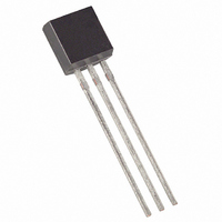
DS18B20+PAR Maxim Integrated Products, DS18B20+PAR Datasheet

DS18B20+PAR
Specifications of DS18B20+PAR
Related parts for DS18B20+PAR
DS18B20+PAR Summary of contents
Page 1
FEATURES • Unique 1-Wire ® interface requires only one port pin for communication • Derives power from data line (“parasite power”)—does not need a local power supply • Multi-drop capability simplifies distributed temperature sensing applications • Requires no external ...
Page 2
DETAILED PIN DESCRIPTIONS Table 1 PIN SYMBOL Ground. 1 GND Data Input/Output pin. Open-drain 1-Wire interface pin. Also provides power the device when used in parasite power mode (see “Parasite Power” section.) No Connect. Doesn’t connect to ...
Page 3
PARASITE POWER The DS18B20-PAR’s parasite power circuit allows the DS18B20-PAR to operate without a local external power supply. This ability is especially useful for applications that require remote temperature sensing or that are very space constrained. Figure 1 shows the ...
Page 4
Table 2 gives examples of digital output data and the corresponding temperature reading for 12-bit resolution conversions. TEMPERATURE REGISTER FORMAT Figure 3 ...
Page 5
The master device can check the alarm flag status of all DS DS18B20-PARs on the bus by issuing an Alarm Search [ECh] command. Any DS18B20-PARs with a set alarm flag will respond to the command, so the master can determine ...
Page 6
DS18B20-PAR MEMORY MAP Figure 6 SCRATCHPAD (Power-up State) byte 0 Temperature LSB (50h) byte 1 Temperature MSB (05h) byte 2 T Register or User Byte 1* H byte 3 T Register or User Byte 2* L byte 4 Configuration Register* ...
Page 7
ROM code CRC (for ROM reads the scratchpad CRC (for scratchpad reads). If the calculated CRC matches the read CRC, the data has been received error free. The comparison of ...
Page 8
HARDWARE CONFIGURATION Figure 9 Micro- processor TRANSACTION SEQUENCE The transaction sequence for accessing the DS18B20-PAR is as follows: Step 1. Initialization Step 2. ROM Command (followed by any required data exchange) Step 3. DS18B20-PAR Function Command ...
Page 9
Search ROM command followed by data exchange) as many times as necessary to identify all of the slave devices. If there is only one slave on the bus, the simpler Read ROM command (see below) can be used ...
Page 10
All three bytes MUST be written before the master issues a reset, or the data may be corrupted. READ SCRATCHPAD [BEh] This command allows the master to read the contents of the scratchpad. The data ...
Page 11
ROM COMMANDS FLOW CHART Figure 10 Initialization Sequence 33h N READ ROM COMMAND Y DS18B20-PAR T X FAMILY CODE 1 BYTE DS18B20-PAR T X SERIAL NUMBER 6 BYTES DS18B20-PAR T X CRC BYTE MASTER T X RESET PULSE DS18B20-PAR T ...
Page 12
DS18B20-PAR FUNCTION COMMANDS FLOW CHART Figure 11 MASTER T X FUNCTION COMMAND N B8h 2 RECALL MASTER BEGINS DATA 2 RECALL FROM E PROM DEVICE BUSY RECALLING DATA ? Y MASTER R “0s” X 44h N CONVERT ...
Page 13
SIGNALING The DS18B20-PAR uses a strict 1-Wire communication protocol to insure data integrity. Several signal types are defined by this protocol: reset pulse, presence pulse, write 0, write 1, read 0, and read 1. All of these signals, with ...
Page 14
The DS18B20-PAR samples the 1-Wire bus during a window that lasts from 15 μ μs after the master initiates the write time slot. If the bus is high during the sampling window written to the ...
Page 15
Therefore, the master must release the bus and then sample the bus state within 15 μs from the start of the slot. Figure 14 illustrates that the sum of T Figure 15 shows that system timing ...
Page 16
MASTER MODE DATA (LSB FIRST data bytes DS18B20-PAR OPERATION EXAMPLE 2 In this example there is only one DS18B20-PAR on the bus. The master writes to the T configuration registers in the DS18B20-PAR scratchpad and then reads the ...
Page 17
ABSOLUTE MAXIMUM RATINGS* Voltage on any pin relative to ground Operating temperature Storage temperature Soldering temperature *These are stress ratings only and functional operation of the device at these or any other conditions above those indicated in the operation sections ...
Page 18
AC ELECTRICAL CHARACTERISTICS PARAMETER SYMBOL Temperature Conversion Time Time to Strong Pullup On Time Slot Recovery Time Write 0 Low Time Write 1 Low Time Read Data Valid Reset Time High Reset Time Low Presence Detect High Presence Detect Low ...
Page 19
TIMING DIAGRAMS Figure DS18B20-PAR ...


