ADT7470ARQZ Analog Devices Inc, ADT7470ARQZ Datasheet - Page 4
ADT7470ARQZ
Manufacturer Part Number
ADT7470ARQZ
Description
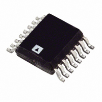
IC SENSOR TEMP FAN CTRLR 16QSOP
Manufacturer
Analog Devices Inc
Datasheet
1.ADT7470ARQZ.pdf
(40 pages)
Specifications of ADT7470ARQZ
Function
Fan Control, Temp Monitor
Topology
ADC, Comparator, Fan Speed Control, Register Bank
Sensor Type
External
Sensing Temperature
External Sensor
Output Type
I²C™
Output Alarm
No
Output Fan
Yes
Voltage - Supply
3 V ~ 5.5 V
Operating Temperature
-40°C ~ 125°C
Mounting Type
Surface Mount
Package / Case
16-QSOP
Ic Output Type
Digital
Sensing Accuracy Range
± 12%
Supply Current
500µA
Supply Voltage Range
3V To 5.5V
Sensor Case Style
QSOP
No. Of Pins
16
Msl
MSL 3 - 168 Hours
Termination Type
SMD
Filter Terminals
SMD
Rohs Compliant
Yes
Accuracy %
12%
Lead Free Status / RoHS Status
Lead free / RoHS Compliant
For Use With
EVAL-ADT7470EBZ - BOARD EVALUATION FOR ADT7470
Lead Free Status / RoHS Status
Lead free / RoHS Compliant, Lead free / RoHS Compliant
Available stocks
Company
Part Number
Manufacturer
Quantity
Price
Company:

Part Number:
ADT7470ARQZ
Manufacturer:
AVX
Quantity:
7 600
Part Number:
ADT7470ARQZ
Manufacturer:
ADI/亚德诺
Quantity:
20 000
Part Number:
ADT7470ARQZ-REEL7
Manufacturer:
ADI/亚德诺
Quantity:
20 000


ADT7470
SERIAL BUS TIMING SPECIFICATIONS
Table 2.
Parameter
SERIAL BUS TIMING
1
2
3
4
5
Typical values are at %A = 25°C and represent the most likely parametric norm.
Logic inputs accept input high voltages up to 5 V even when the device is operating at supply voltages below 5 V.
VDD should never be floated in the presence of SCL/SDA activity. Charge injection can be sufficient to induce approximately 0.6 V on VDD.
All voltages are measured with respect to GND, unless otherwise specified.
Timing specifications are tested at logic levels of VIL = 0.8 V for a falling edge and VIH = 2.0 V for a rising edge.
Clock Frequency, f
Glitch Immunity, t
Bus Free Time, t
Start Setup Time, t
Start Hold Time, t
SCL Low Time, t
SCL High Time, t
SCL, SDA Rise Time, t
SCL, SDA Fall Time, t
Data Setup Time, t
Detect Clock Low Timeout, t
SDA
SCL
1, 2, 3, 4, 5
P
BUF
LOW
t
HIGH
BUF
HD;STA
SW
SCLK
SU;DAT
SU;STA
S
f
r
t
HD;STA
TIMEOUT
t
LOW
t
R
t
HD;DAT
t
Figure 2. Serial Bus Timing Diagram
HIGH
t
F
t
SU;DAT
Rev. C | Page 4 of 40
Min
1.3
600
600
1.3
0.6
100
25
Typ
50
28
S
Max
400
300
300
31
t
SU;STA
t
HD;STA
Unit
kHz
ns
μs
ns
ns
μs
μs
ns
ns
ns
ms
Test Conditions/Comments
See Figure 2
See Figure 2
See Figure 2
See Figure 2
See Figure 2
See Figure 2
See Figure 2
See Figure 2
See Figure 2
See Figure 2
Can be optionally disabled,
via Configuration Register 1
(see Table 6)
t
SU;STO
P
Related parts for ADT7470ARQZ
Image
Part Number
Description
Manufacturer
Datasheet
Request
R

Part Number:
Description:
±1.7g Dual-Axis IMEMS Accelerometer Evaluation Board
Manufacturer:
Analog Devices Inc
Datasheet:

Part Number:
Description:
Inertial Sensor Evaluation System
Manufacturer:
Analog Devices Inc
Datasheet:
Part Number:
Description:
Manufacturer:
Analog Devices Inc
Datasheet:
Part Number:
Description:
Manufacturer:
Analog Devices Inc
Datasheet:
Part Number:
Description:
Manufacturer:
Analog Devices Inc
Datasheet:
Part Number:
Description:
Manufacturer:
Analog Devices Inc
Datasheet:
Part Number:
Description:
Manufacturer:
Analog Devices Inc
Datasheet:
Part Number:
Description:
Manufacturer:
Analog Devices Inc
Datasheet:
Part Number:
Description:
Manufacturer:
Analog Devices Inc
Datasheet:
Part Number:
Description:
Manufacturer:
Analog Devices Inc
Datasheet:
Part Number:
Description:
Manufacturer:
Analog Devices Inc
Datasheet:
Part Number:
Description:
Manufacturer:
Analog Devices Inc
Datasheet:
Part Number:
Description:
Manufacturer:
Analog Devices Inc
Datasheet: