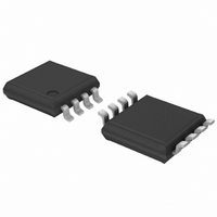
SA56004EDP,118 NXP Semiconductors, SA56004EDP,118 Datasheet - Page 18

SA56004EDP,118
Manufacturer Part Number
SA56004EDP,118
Description
IC TEMP SENSOR 8-TSSOP
Manufacturer
NXP Semiconductors
Datasheet
1.SA56004BDP118.pdf
(36 pages)
Specifications of SA56004EDP,118
Package / Case
8-TSSOP
Output Type
I²C™/SMBus™
Function
Temp Monitoring System (Sensor)
Topology
ADC (Sigma Delta), Multiplexer, Register Bank
Sensor Type
External & Internal
Sensing Temperature
-40°C ~ 125°C, External Sensor
Output Alarm
Yes
Output Fan
Yes
Voltage - Supply
3 V ~ 3.6 V
Operating Temperature
-40°C ~ 125°C
Mounting Type
Surface Mount
Supply Voltage (max)
5.5 V
Supply Voltage (min)
3 V
Maximum Operating Temperature
+ 125 C
Minimum Operating Temperature
- 40 C
Supply Current
1 mA
Lead Free Status / RoHS Status
Lead free / RoHS Compliant
For Use With
568-3615 - DEMO BOARD I2C
Lead Free Status / Rohs Status
Lead free / RoHS Compliant
Other names
568-3338-2
935274567118
SA56004EDP-T
935274567118
SA56004EDP-T
NXP Semiconductors
SA56004X_5
Product data sheet
7.10 SMBus interface
LOW. Furthermore, if the Remote HIGH Setpoint High Byte (RHSHB) register is set to a
value less than +127 C and the Alert Mask is disabled, then the ALERT output will be
pulled LOW. Note that the OPEN bit itself will not trigger an ALERT.
When the D+ pin is shorted to ground or to D , the Remote Temperature High Byte
(RTHB) register is loaded with 128 C (1000 0000) and the OPEN (bit 2 in the Status
register) will not be set. Since operating the SA56004X is beyond its normal limits, this
temperature reading represents this shorted fault condition. If the value in the Remote
Low Setpoint High Byte (RLSHB) register is more than 128 C and the Alert Mask is
disabled, the ALERT output will be pulled LOW.
The device can communicate over a standard two-wire serial interface System
Management Bus (SMBus) or compatible I
employs four standard SMBus protocols: Write Byte, Read Byte, Receive Byte, and
Send Byte. Data formats of four protocols are shown in
of protocol are important:
•
•
•
•
•
The SMBus master initiates data transfer by establishing a START condition (S) and
terminates data transfer by generating a STOP condition (P).
Data is sent over the serial bus in sequences of 9 clock pulses according to each 8-bit
data byte followed by 1-bit status of device acknowledgement (A).
The 7-bit slave address is equivalent to factory-programmed address of the device.
The command byte is equivalent to the address of the selected device register.
The Receive Byte format is used for quicker transfer data from a device reading
register that was previously selected.
Rev. 05 — 22 May 2008
Digital temperature sensor with overtemperature alarms
2
C-bus using SCLK and SDATA. The device
Figure
9. The following key points
SA56004X
© NXP B.V. 2008. All rights reserved.
18 of 36


