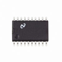
LM2635MX National Semiconductor, LM2635MX Datasheet - Page 2

LM2635MX
Manufacturer Part Number
LM2635MX
Description
IC REG SYNCH BUCK 5-BIT 20-SOIC
Manufacturer
National Semiconductor
Datasheet
1.LM2635MNOPB.pdf
(13 pages)
Specifications of LM2635MX
Applications
Power Supplies
Current - Supply
2.5mA
Voltage - Supply
4.5 V ~ 5.5 V
Operating Temperature
0°C ~ 125°C
Mounting Type
Surface Mount
Package / Case
20-SOIC (7.5mm Width)
Lead Free Status / RoHS Status
Lead free / RoHS Compliant
Other names
*LM2635MX
LM2635MXTR
LM2635MXTR
Available stocks
Company
Part Number
Manufacturer
Quantity
Price
Company:
Part Number:
LM2635MX
Manufacturer:
FUJITSU
Quantity:
2
Part Number:
LM2635MX
Manufacturer:
NS/国半
Quantity:
20 000
Company:
Part Number:
LM2635MX/NOPB
Manufacturer:
NXP
Quantity:
3 050
www.national.com
Connection Diagram
Pin Descriptions
LSGATE (Pin 1): Gate drive for the low-side N-channel
MOSFET. This signal is interlocked with HSGATE (Pin 20) to
avoid a shoot-through problem.
BOOTV (Pin 2): Power supply for high-side N-channel
MOSFET gate drive. The voltage should be at least one gate
threshold above the converter input voltage to properly op-
erate the high-side N-FET.
PGND (Pin 3): Ground for high current circuitry. It should be
connected to system ground.
SGND (Pin 4): Ground for signal level circuitry. It should be
connected to system ground.
V
SENSE (Pin 6): Converter output voltage sensing. It pro-
vides input for power good, fast dual comparator control
loop, and over-voltage protection circuitry. It is recom-
mended that a 0.1 µF capacitor be connected between this
pin and ground to avoid potential noise problems.
IMAX (Pin 7): Current limit threshold setting. It sinks a fixed
180 µA current. By connecting a resistor between the high
side MOSFET drain and this pin, a fixed voltage drop can be
built across the resistor. This voltage drop is compared with
the V
over-current condition has occurred.
CC
(Pin 5): Power supply for the controller.
DS
of the high-side N-MOSFET to determine if an
See NS Package Number M20B
Order Number LM2635M
Plastic SO-20
TOP VIEW
10011903
2
IFB (Pin 8): High-side N-MOSFET source voltage sensing.
This pin is one V
lower than that of IMAX pin during the time the high-side FET
is on, it means V
the IMAX resistor, which can be interpreted as an over-
current condition.
V
mainly for use by other power supplies on the motherboard
which need a reference.
EA_OUT (Pin 10): Output of the error amplifier. The voltage
level on this pin is compared with an internally generated
ramp signal to determine the duty cycle. This pin is neces-
sary for compensating the primary control loop.
FB (Pin 11): Inverting input of the error amplifier. A pin
necessary for compensating the control loop.
FREQ_ADJ (Pin 12): Switching frequency adjustment.
Switching frequency can be adjusted by changing the
grounding resistance on this pin.
PWRGD (Pin 13): Power Good. There are two windows
around the DAC output voltage that are associated with
PWRGD pin, the
PWRGD is initially high (open drain state) and output voltage
travels out of
impedance to ground). If PWRGD is initially low and output
voltage travels into the
the window for at least 10 ms, PWRGD goes to high. A
PWRGD high means the output voltage is at least within the
±
voltage is definitely outside the
VID4:0 (Pins 14, 15, 16, 17, 18): Voltage Identification
Code. The five pins accept an open-ground pattern 5-bit
binary code from outside the chip (typically from the CPU) for
generating the desired output voltage. Each VID pin is inter-
nally pulled up to V
shows the code table.
OUTEN (Pin 19): Output Enable. The output voltage is
disabled when this pin is pulled low. It is internally pulled up
to V
HSGATE (Pin 20): Gate drive for the high-side N-channel
MOSFET. This signal is interlocked with LSGATE (Pin 1) to
avoid a shoot-through problem.
REF
10% window whereas a PWRGD low indicates the output
CC
(Pin 9): Bandgap reference voltage. This voltage is
via a 90 µA current source.
±
DS
DS
10% window, PWRGD goes to low (low
±
below drain voltage. When this voltage is
CC
is higher than the preset voltage across
10% window and the
via a 90 µA current source. Table 1
±
8% window and has stayed within
±
8% window.
±
8% window. If


