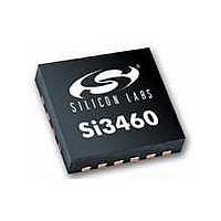
SI3460-E03-GM Silicon Laboratories Inc, SI3460-E03-GM Datasheet - Page 13

SI3460-E03-GM
Manufacturer Part Number
SI3460-E03-GM
Description
IC POWER MANAGEMENT CTLR 11VQFN
Manufacturer
Silicon Laboratories Inc
Datasheet
1.SI3460-E02-GMR.pdf
(24 pages)
Specifications of SI3460-E03-GM
Package / Case
11-VQFN
Applications
Power Sourcing Equipment (PSE)
Current - Supply
500mA
Voltage - Supply
2.7 V ~ 3.6 V
Operating Temperature
-40°C ~ 85°C
Mounting Type
Surface Mount
Product
PoE / LAN Solutions
Supply Voltage (max)
16 V
Supply Voltage (min)
11 V
Operating Temperature Range
- 40 C to + 85 C
Mounting Style
SMD/SMT
Operating Temperature (max)
85C
Operating Temperature (min)
-40C
Pin Count
11
Mounting
Surface Mount
Package Type
QFN EP
Case Length
3mm
Case Height
0.83mm
Screening Level
Industrial
Lead Free Status / RoHS Status
Lead free / RoHS Compliant
Lead Free Status / RoHS Status
Lead free / RoHS Compliant, Lead free / RoHS Compliant
Available stocks
Company
Part Number
Manufacturer
Quantity
Price
Company:
Part Number:
SI3460-E03-GM
Manufacturer:
SAMSUNG
Quantity:
1 400
Company:
Part Number:
SI3460-E03-GM
Manufacturer:
Silicon Laboratories Inc
Quantity:
135
Si3460
4.3.4. DC-DC Converter Ramp-Up
After the optional classification sequence, the dc-dc converter is powered up to –50 V with a current limit
corresponding to the values indicated in Table 9. After powerup, power is applied to V
as long as there is not an
OUT
overcurrent fault, disconnect, or input undervoltage (UVLO) condition. The STATUS LED is continuously lit when
power is applied. If the output power exceeds the level determined by the initial voltage of the STATUS pin, the
Si3460 will declare an error and shut down the port, flashing the LED rapidly to indicate the error (for either two
seconds or until reset as determined by the initial voltage on the STATUS pin).
4.3.5. DC-DC Converter Soft Start
The PWM control loop of the dc-dc converter is designed to produce a gradual rise in output voltage to eliminate
any inrush current issues. The nominal set point of the dc-dc converter is –50 V. V
at –50 V results in 0.930 V
OUT
at the VSENSE pin. It is possible for there to be almost no load on the dc-dc converter; so, the duty cycle is ramped
slowly up to the dc set point. The duty cycle is initially set to zero (dc-dc converter off). Once the desired voltage set
point is reached, the feedback path from VSENSE is enabled, and the converter is allowed to regulate at the
desired set point.
4.3.6. Disconnect
The Si3460 implements a robust disconnect algorithm. If the output current level drops below 7.5 mA (nominal) for
more than 350 ms, the Si3460 will declare a PD disconnect, and the dc-dc converter clock (250 kHz) and FET M1
will be turned off. As set by the initial voltage on the STATUS pin, the Si3460 will then automatically resume the
detection process after 250 ms for "endpoint mode" and two seconds for "midspan mode." The difference in these
two backoff timings is specified by the IEE 802.3af standard for the midspan and endpoint operating modes.
4.3.7. Current Limit Control
The Si3460's overcurrent trip point is determined by the output power set during the classification stage power
granting process. If the output current exceeds the threshold, a timer counts up towards a time-out of 60 ms. If the
current drops below the set threshold, the timer counts down towards zero at 1/16th the rate. If the timer reaches
60 ms, an overcurrent fault is declared, and the channel is shut down by turning off the dc-dc converter clock and
then turning off the FET M1. After an overcurrent fault event, the LED will flash rapidly.
As set by the initial voltage on the STATUS pin at powerup, the Si3460 will then automatically resume the detection
process for "automatic restart configuration" unless the Si3460 is configured in a "restart after a RESET condition"
mode and a fault condition is detected; in that case, the LED will flash rapidly, and the detection process will
automatically start again after 2.2 seconds. Power will not be provided until an open-circuit condition is detected.
Once the Si3460-EVB detects an open-circuit condition (normally by removing the Ethernet cable from the Si3460-
EVB’s RJ-45 jack labelled “To PD”), the detection process begins, the status LED blinks at the rate of 3 times per
second, and the Si3460 is then allowed to go into classification and powerup mode if a valid PD signature
resistance is detected.
4.3.8. UVLO
The Si3460-EVB reference design is optimized for 12 to 15 V nominal input voltages (11 V min to 16 V maximum).
If the input voltage drops below 10 V in detection mode or if the output voltage drops below 10 V in classification or
powerup mode, a UVLO condition is declared, which generates the error condition (LED flashing rapidly). An
undervoltage event is a fault condition reported through the status LED as a rapid blinking of 10 flashes per
second. The UVLO condition is continuously monitored in all operating states.
4.3.9. Status LED Function
During the normal detection sequence, the STATUS LED flashes at approximately 3 times per second as the
detection process continues. After successful power up, the LED glows continuously. If there is an error condition
(i.e., class level is beyond programmed value, or a fault or over current condition has been detected), the LED
flashes rapidly at 10 times per second). This occurs for two seconds for normal error delay and, in the case of the
"restart after a RESET condition", the LED will flash rapidly, and the detection process will automatically start again
after 2.2 s and power will not be provided until an open circuit condition is detected. Once the Si3460-EVB detects
an open circuit condition, the LED blinks at 3 times per second.
If the Powered Device (PD) is disconnected so that a disconnect event occurs, the LED will start flashing at 3 times
per second once the detect process resumes.
Rev. 1.1
13


