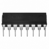
TCA785 Infineon Technologies, TCA785 Datasheet - Page 2

TCA785
Manufacturer Part Number
TCA785
Description
IC PHASE CONTROL 250MA OUT 16DIP
Manufacturer
Infineon Technologies
Type
Phase Control ICr
Datasheet
1.TCA785.pdf
(16 pages)
Specifications of TCA785
Package / Case
16-DIP (0.300", 7.62mm)
Applications
Multiphase Controller
Current - Supply
6.5mA
Voltage - Supply
8 V ~ 18 V
Operating Temperature
-25°C ~ 85°C
Mounting Type
Through Hole
Maximum Operating Temperature
+ 85 C
Minimum Operating Temperature
- 25 C
Mounting Style
Through Hole
Lead Free Status / RoHS Status
Lead free / RoHS Compliant
Lead Free Status / RoHS Status
Lead free / RoHS Compliant, Lead free / RoHS Compliant
Other names
SP000011719
TCA785
TCA785IN
TCA785X
TCA785XK
TCA785XTIN
TCA785XTIN
TCA785
TCA785IN
TCA785X
TCA785XK
TCA785XTIN
TCA785XTIN
Available stocks
Company
Part Number
Manufacturer
Quantity
Price
Company:
Part Number:
TCA785
Manufacturer:
INFINEON
Quantity:
334
Company:
Part Number:
TCA785
Manufacturer:
SIEMENS
Quantity:
5 510
Part Number:
TCA785
Manufacturer:
INFINEON/英飞凌
Quantity:
20 000
Company:
Part Number:
TCA785HKLA1
Manufacturer:
MARVELL
Quantity:
450
Company:
Part Number:
TCA785P
Manufacturer:
SIEMENS
Quantity:
5 510
Part Number:
TCA785P
Manufacturer:
INFINEON/英飞凌
Quantity:
20 000
Functional Description
The synchronization signal is obtained via a high-ohmic resistance from the line voltage
(voltage V
synchronization register.
This synchronization register controls a ramp generator, the capacitor C
by a constant current (determined by R
V
control voltage V
For every half wave, a positive pulse of approx. 30 s duration appears at the outputs Q 1 and
Q 2. The pulse duration can be prolonged up to 180˚ via a capacitor C
to ground, pulses with a duration between
Outputs
A signal of
A signal which corresponds to the NOR link of Q 1 and Q 2 is available at output Q Z (pin 7).
The inhibit input can be used to disable outputs Q1, Q2 and
Pin 13 can be used to extend the outputs
Semiconductor Group
Block Diagram
11
(triggering angle ), a signal is processed to the logic. Dependent on the magnitude of the
Q 1
5
). A zero voltage detector evaluates the zero passages and transfers them to the
+180˚ which can be used for controlling an external logic,is available at pin 3.
and
11
, the triggering angle
Q 2
supply the inverse signals of Q 1 and Q 2.
9
). If the ramp voltage V
can be shifted within a phase angle of 0˚ to 180˚.
Q 1
and 180˚ will result.
2
and
Q 2
to full pulse length (180˚ – ).
Q 1
10
exceeds the control voltage
,
Q 2
12
. If pin 12 is connected
10
.
of which is charged
TCA 785


