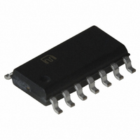
MIC2561-0BM Micrel Inc, MIC2561-0BM Datasheet - Page 7

MIC2561-0BM
Manufacturer Part Number
MIC2561-0BM
Description
IC PCMCIA CARD SW MATRIX 14-SOIC
Manufacturer
Micrel Inc
Type
PCMCIA/Cardbus Switchr
Datasheet
1.MIC2561-1YM.pdf
(12 pages)
Specifications of MIC2561-0BM
Number Of Outputs
2
Rds (on)
1 Ohm
Internal Switch(s)
Yes
Current Limit
200mA
Voltage - Input
3.3V, 5V, 12V
Operating Temperature
0°C ~ 70°C
Mounting Type
Surface Mount
Package / Case
14-SOIC (3.9mm Width), 14-SOL
Lead Free Status / RoHS Status
Contains lead / RoHS non-compliant
Available stocks
Company
Part Number
Manufacturer
Quantity
Price
Part Number:
MIC2561-0BM
Manufacturer:
MICREL/麦瑞
Quantity:
20 000
Figure 4. MIC2561 Typical PCMCIA memory card application with dual V
driven together.
However, many cost sensitive designs (especially notebook/
palmtop computers) connect V
is not required. This circuit is shown in Figure 4.
When a memory card is initially inserted, it should receive
V
determined by a combination of mechanical socket “keys”
and voltage sense pins. The card sends a handshaking data
stream to the controller, which then determines whether or
not this card requires V
V
level, the controller commands this change by disabling V
waiting at least 100ms, and then re-enabling the other V
voltage.
If no card is inserted or the system is in sleep mode, the
controller outputs a (V
MIC2561, which shuts down V
into a high impedance output shutdown (sleep) mode, where
current consumption drops to nearly zero, with only tiny
CMOS leakage currents flowing.
During Flash memory programming with standard (+12V)
Flash memories, the PCMCIA controller outputs a (1,0) to the
EN0, EN1 control pins of the MIC2561, which connects
V
switches allow using small bypass capacitors (in some cases,
none at all) on the V
filtering action performed by a large filter capacitor on the
input supply voltage to V
supply filter capacitor is sufficient). The V
from V
completed, the controller outputs a (EN1, EN0) = (0,1) to the
MIC2561, which then reduces V
read verification. Break-before-make switching action re-
duces switching transients and lowers maximum current
spikes through the switch from the output capacitor. The flag
comparator prevents having high voltage on the V
capacitor from contaminating the V
low voltage V
January 2005
MIC2561
CC
CC
PP
. If the card is compatible with and desires a different V
IN to V
— either 3.3V ± 0.3V or 5.0V ±5%. The initial voltage is
CC
to 12.0V typically takes 15µs. After programming is
PP OUT
PP
switches until V
. The low ON resistance of the MIC2561
CC OUT
PP
CC3
and if the card is designed for dual
PP
and V
IN, V
CC
PP1
IN (usually the main power
PP OUT
Controller
PP OUT
Card Slot
. This also places the switch
System
Supply
PCMCIA
Power
PP OUT
CC
to V
CC5
inputs, by disabling the
PP2
drops below the V
3.3V
to the V
12V
IN) = (0,0) to the
pins, with the main
5V
PP OUT
and the MIC2557
CC
transition
level for
PP OUT
CC
CC
CC
CC
,
EN0
EN1
V CC5_EN
V CC3_EN
7
V PP IN
level selected. The lockout delay time varies with the load
current and the capacitor on V
and nominal I
Internal drive and bias voltage is derived from V
device control logic is powered from V
threshold voltages are compatible with common PCMCIA
controllers using either 3.3V or 5V supplies. No pull-up
resistors are required at the control inputs of the MIC2561.
Output Current and Protection
MIC2561 output switches are capable of more current than
needed in PCMCIA applications and meet or exceed all
PCMCIA specifications. For system and card protection,
output currents are internally limited. For full system protec-
tion, long term (millisecond or longer) output short circuits
invoke overtemperature shutdown, protecting the MIC2561,
the system power supplies, the card socket pins, and the
memory card. The MIC2561 overtemperature shutdown oc-
curs at a die temperature of 110°C.
Suspend Mode
An additional feature in the MIC2561 is a pseudo power-down
mode, Suspend Mode, which allows operation without a V
IN supply. In Suspend Mode, the MIC2561 supplies 3.3V to
V
PCMCIA controller. This mode allows the system designer
the ability to turn OFF the V
power when it is not specifically required. The PCMCIA card
receives V
the switch resistance rises to approximately 4.5Ω.
High Current V
+12V Supply
Figure 5 shows the MIC2561 with V
by a simple charge pump. This enables the system designer
to achieve full V
which is often helpful in battery powered systems that only
provide +12V when it is needed. These on-demand +12V
MIC2561
CC
V CC3 IN
OUT whenever a V
V CC5 IN
CC
PP OUT
CC
at reduced capacity during Suspend Mode, as
(5.0V or 3.3V). Note that V
V PP1
V PP2
V CC
CC
CC
, the delay is approximately 250µs.
performance without a +12V supply,
Card Slot
Operation Without a
PCMCIA
CC
output of 3.3V is enabled by the
PP OUT
PP
supply generator to save
CC
. With a 0.1µF capacitor
switch bias provided
CC3
PP1
IN. Input logic
PP
and V
IN. Internal
MIC2561
PP2
Micrel
are
PP


