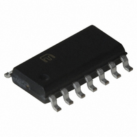
MIC2561-0BM Micrel Inc, MIC2561-0BM Datasheet - Page 6

MIC2561-0BM
Manufacturer Part Number
MIC2561-0BM
Description
IC PCMCIA CARD SW MATRIX 14-SOIC
Manufacturer
Micrel Inc
Type
PCMCIA/Cardbus Switchr
Datasheet
1.MIC2561-1YM.pdf
(12 pages)
Specifications of MIC2561-0BM
Number Of Outputs
2
Rds (on)
1 Ohm
Internal Switch(s)
Yes
Current Limit
200mA
Voltage - Input
3.3V, 5V, 12V
Operating Temperature
0°C ~ 70°C
Mounting Type
Surface Mount
Package / Case
14-SOIC (3.9mm Width), 14-SOL
Lead Free Status / RoHS Status
Contains lead / RoHS non-compliant
Available stocks
Company
Part Number
Manufacturer
Quantity
Price
Part Number:
MIC2561-0BM
Manufacturer:
MICREL/麦瑞
Quantity:
20 000
MIC2561
Applications Information
PCMCIA V
the MIC2561 voltage selector/switch IC. Four control bits
determine V
operate mode condition. V
(3.3V or 5V), V
When the V
device switches into “sleep” mode and draws only nano-
amperes of leakage current. An error flag falls low if the output
is improper, because of overtemperature or overcurrent
faults. Full protection from hot switching is provided which
prevents feedback from the V
12V to 5V, for example) by locking out the low voltage switch
until V
protected against 5V to 3.3V shoot through.
The MIC2561 is a low-resistance power MOSFET switching
matrix that operates from the computer system main power
supply. Device logic power is obtained from V
internal MOSFET drive is obtained from the V
(usually +12V) during normal operation. If +12V is not avail-
able, the MIC2561 automatically switches into “suspend”
mode, where V
switch resistance. Internal break-before-make switches de-
termine the output voltage and device mode.
Figure 3. MIC2561 Typical PCMCIA memory card application with dual V
MIC2561
PP OUT
CC
CC
CC OUT
drops below V
and V
CC OUT
PP
high impedance condition is selected, the
, or a high impedance state are available.
PP
and V
can be switched to 3.3V, but at higher
control is easily accomplished using
Controller
Card Slot
System
PCMCIA
Supply
Power
PP OUT
PP OUT
CC
PP OUT
. The V
3.3V
12V
output voltages of V
5V
to the V
voltage and standby/
CC
output is similarly
EN0
EN1
CC
V PP IN V DD
inputs (from
MIC2557
PP
CC3
V PP OUT
IN pin
and
V CC
CC
EN0
EN1
V CC5_EN
V CC3_EN
6
V PP IN
Supply Bypassing
External capacitors are not required for operation. The
MIC2561 is a switch and has no stability problems. For best
results however, bypass V
inputs with filter capacitors to improve output ripple. As all
internal device logic and voltage/current comparison func-
tions are powered from the V
line is the most critical, and may be necessary in some cases.
In the most stubborn layouts, up to 0.47µF may be necessary.
Both V
capacitors for noise reduction and electrostatic discharge
(ESD) damage prevention. Larger values of output capacitor
might create current spikes during transitions, requiring larger
bypass capacitors on the V
PCMCIA Implementation
The Personal Computer Memory Card International Associa-
tion (PCMCIA) specification requires two V
PCMCIA slot. V
(EEPROM) memory cards. The two V
programmed to different voltages. Fully implementing PCM-
CIA specifications requires a MIC2561, a MIC2557 PCMCIA
V
full configuration, supporting both 5.0V and 3.3V V
tion.
PP
MIC2561
V CC3 IN
Switching Matrix, and a controller. Figure 3 shows this
CC OUT
V CC5 IN
CC
and V
PP
(5.0V or 3.3V) and separate V
is primarily used for programming Flash
PP OUT
V PP1
V PP2
V CC
CC3
CC3
CC3
pins may have 0.01µF to 0.1µF
Card Slot
IN, V
PCMCIA
IN line, supply bypass of this
IN, V
CC5
PP
CC5
IN, and V
supply pins may be
PP
IN, and V
supply pins per
January 2005
PP1
PP
CC
and V
IN pins.
opera-
Micrel
PP
PP2.
IN


