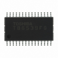
TB6539FG(EL) Toshiba, TB6539FG(EL) Datasheet - Page 9

TB6539FG(EL)
Manufacturer Part Number
TB6539FG(EL)
Description
IC MOTOR CTRL DC MOTOR 30SSOP
Manufacturer
Toshiba
Type
3 Phase Full Wave Sine Wave PWM Brushless Motor Controllerr
Datasheet
1.TB6539NG.pdf
(20 pages)
Specifications of TB6539FG(EL)
Applications
DC Motor Controller, Brushless (BLDC), 3 Phase
Number Of Outputs
1
Voltage - Load
4.5 V ~ 18 V
Voltage - Supply
10 V ~ 18 V
Operating Temperature
-30°C ~ 115°C
Mounting Type
Surface Mount
Package / Case
30-SSOP
Operating Supply Voltage
10 V to 18 V
Supply Current
30 mA
Mounting Style
SMD/SMT
Lead Free Status / RoHS Status
Lead free / RoHS Compliant
Current - Output
-
Lead Free Status / Rohs Status
Lead free / RoHS Compliant
Other names
TB6539FGTR
Functional Description
Basic operation
Function to stabilize bootstrap voltage
Dead time function: upper/lower transistor output off-time
Correcting lead angle
Setting carrier frequency
Switching the output of turn-on signal
Outputting reverse rotation detection signal
the positional signal reaches number of rotations f = 5 Hz or higher, the rotor position is inferred from the
positional signal and a modulation wave is generated. The modulation wave and the triangular wave are
compared; the sine-wave PWM signal is then generated and the motor is driven.
(1)
(2)
short circuit caused by the simultaneous turning on of upper and lower external power devices.
voltage.
square wave.)
immediately after reset.)
On start-up, the motor is driven by the square-wave turn-on signal based on a positional signal. When
When the motor is driven by a sine-wave PWM, dead time is generated digitally in the IC to prevent any
The lead angle can be corrected in the turn-on signal range from 0 to 58° in relation to the induced
Analog input from LA pin (0 to 5 V divided by 32):
This feature sets the triangular wave cycle (carrier cycle) necessary for generating the PWM signal.
(The triangular wave is used for forcibly turning on the lower transistor when the motor is driven by
This function switches the output of the turn-on signal between high and low.
Pin OS:
The direction of motor rotation is detected for every electrical angle of 360°. (The output is high
The REV terminal increases to a 180° turn-on mode at the time of High-Z.
CW/CCW Pin
From start to 5 Hz: When driven by square wave (120° turn-on), f = f
5 Hz~: When driven by sine-wave PWM (180° turn-on)
Dead time: T
f
0 V = 0°
5 V = 58° (when more than 5 V is input, 58°)
Carrier cycle = f
High = active high
Low = active low
High (CCW)
osc
Low (CW)
When voltage instruction is input at V
When voltage instruction is input at V
(On duty is approx. 8%.)
Note: At startup, to charge the upper transistor gate power supply, turn the lower transistor on for a fixed
The lower transistor is turned on at the regular (carrier) cycle. (On duty is approx. 8%.)
During sine-wave drive, the drive signal is output as it is.
During square-wave drive, the lower transistor is forcibly turned on at the regular (carrier) cycle.
= reference clock (crystal oscillation)
time with V
d
= 16/f
osc
Actual Motor Rotating Direction
e
/252 (Hz)
< = 0.2 V.
osc
(s)
CCW (reverse)
CCW (reverse)
CW (forward)
CW (forward)
e
e
< = 0.2 V:
> 0.2 V:
9
When f
f
osc
= reference clock (crystal oscillation)
REV Pin
High-Z
High-Z
Low
Low
osc
= 4 MHz, approx. T
When f
osc
/(2
osc
12
TB6539N/NG/F/FG
= 4 MHz, approx. 5 Hz
d
× 32 × 6)
= 4 µ s.
2007-07-17


