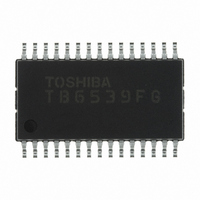
TB6539FG(EL) Toshiba, TB6539FG(EL) Datasheet - Page 14

TB6539FG(EL)
Manufacturer Part Number
TB6539FG(EL)
Description
IC MOTOR CTRL DC MOTOR 30SSOP
Manufacturer
Toshiba
Type
3 Phase Full Wave Sine Wave PWM Brushless Motor Controllerr
Datasheet
1.TB6539NG.pdf
(20 pages)
Specifications of TB6539FG(EL)
Applications
DC Motor Controller, Brushless (BLDC), 3 Phase
Number Of Outputs
1
Voltage - Load
4.5 V ~ 18 V
Voltage - Supply
10 V ~ 18 V
Operating Temperature
-30°C ~ 115°C
Mounting Type
Surface Mount
Package / Case
30-SSOP
Operating Supply Voltage
10 V to 18 V
Supply Current
30 mA
Mounting Style
SMD/SMT
Lead Free Status / RoHS Status
Lead free / RoHS Compliant
Current - Output
-
Lead Free Status / Rohs Status
Lead free / RoHS Compliant
Other names
TB6539FGTR
Operating Waveform When Driven by Square Wave
Hall signal
Output waveform
Note: The motor is driven by a square wave if REV = Low, i.e., if the Hall signals at start-up are 5 Hz (fosc = 4 MHz)
To stabilize the bootstrap voltage, the lower outputs (X, Y, and Z) are always turned on at the carrier cycle
even during off time. At that time, the upper outputs (U, V, and W) are assigned dead time and turned off
at the timing when the lower outputs are turned on. (T
When the motor is driven by a square wave, acceleration or deceleration is determined by voltage V
motor accelerates or decelerates according to the On duty of T
page 11.)
or lower and the motor is rotating in the reverse direction to that of the TB6551F/FG setting.
H
H
H
W
W
U
V
Y
U
X
V
Z
Carrier cycle = f
T
ONL
W
Z
= carrier cycle × 8% (s) (uniform regardless of Ve input)
osc
/252 (Hz)
T
ONU
waveform
Enlarged
T
d
14
T
ONL
T
Dead time: T
d
d
varies with input V
ONU.
(CW/CCW = Low, OS = High)
d
(See the diagram for output On duty on
= 16/f
osc
e.
)
(s) (when V
TB6539N/NG/F/FG
e
= 4.6 V or more)
2007-07-17
e
. The


