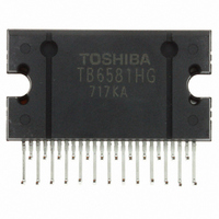
TB6581HG Toshiba, TB6581HG Datasheet - Page 7

TB6581HG
Manufacturer Part Number
TB6581HG
Description
IC BRUSHLESS MOTOR CTLR 25HZIP
Manufacturer
Toshiba
Type
3 Phase Full Wave Sine Wave PWM Brushless Motor Controllerr
Datasheet
1.TB6581HG.pdf
(15 pages)
Specifications of TB6581HG
Applications
DC Motor Controller, Brushless (BLDC), 3 Phase
Number Of Outputs
1
Current - Output
1A
Voltage - Load
50 V ~ 400 V
Voltage - Supply
13.5 V ~ 16.5 V
Operating Temperature
-30°C ~ 115°C
Mounting Type
Through Hole
Package / Case
25-HZIP
Product
Fan / Motor Controllers / Drivers
Operating Supply Voltage
15 V, 7 V
Supply Current
3 mA, 6 mA
Mounting Style
SMD/SMT
Lead Free Status / RoHS Status
Lead free / RoHS Compliant
Available stocks
Company
Part Number
Manufacturer
Quantity
Price
Company:
Part Number:
TB6581HG
Manufacturer:
Toshiba
Quantity:
10
Company:
Part Number:
TB6581HG
Manufacturer:
NORTEL
Quantity:
89
Part Number:
TB6581HG
Manufacturer:
TOSHIBA/东芝
Quantity:
20 000
5. Setting the carrier frequency
6. Outputting the reverse rotation detection signal
7. Protecting input pin
square wave.)
whether the actual direction of a rotating motor coincides with that of the internal reference voltage.
(1)
(2)
(3)
This function sets the triangular wave cycle (carrier cycle) necessary for generating the PWM signal.
(The triangular wave is used for forcibly turning on the lower transistor when the motor is driven by
This function detects the motor rotation direction every electrical angle of 360°. This function judges
*: CW or CCW of the motor is determined by the direction of the Hall signal, which is specified in the timing
*: When the REV pin is set to LOW, and the Hall signal is higher than 5 Hz, sine-wave drive mode is turned
Actual Motor Rotating Direction
Carrier cycle = f
Overcurrent protection (Pin I
Overcurrent protection is released for each carrier frequency.
Positional signal abnormality protection
Monitor protection for V
turned off and the motor is stopped when there is a power supply fault.
chart on page 9.
on.
When the DC-link-current exceeds the internal reference voltage, gate block protection is performed.
Reference voltage = 0.5 V (typ.)
Output is turned off when the positional signal is HHH or LLL; otherwise, it is restarted.
For power supply on/off outside the operating voltage range, the U, V and W drive outputs are
< V
< V
Power supply voltage 11.5 V (typ.)
CCW (reverse)
CW (forward)
Power supply voltage 4.5 V (typ.)
CC7
Turn-on drive output
CC15
Turn-on drive output
>
>
Turn-off drive output
Turn-off drive output
osc
/252 (Hz)
CC7
/ V
dc
f
REV Pin
CC15
osc
)
HIGH
LOW
= reference clock (crystal oscillation)
low supply voltage
7
Sine-wave waveform (180° turn-on mode)
Square waveform (120° turn-on mode)
Output
Output
Drive Mode
4.0 V (typ.)
11.0 V (typ.)
Turn-off drive output
Turn-off drive output
V
V
GND
V
GND
V
CC7
CC15
B
B
TB6581H/HG
2006-03-02


