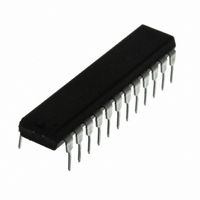
L6229N STMicroelectronics, L6229N Datasheet - Page 5

L6229N
Manufacturer Part Number
L6229N
Description
IC MOTOR DRIVER 3PHASE 24-PWRDIP
Manufacturer
STMicroelectronics
Type
Driverr
Datasheet
1.L6229DTR.pdf
(25 pages)
Specifications of L6229N
Applications
DC Motor Driver, Brushless (BLDC), 3 Phase
Number Of Outputs
1
Current - Output
2.8A
Voltage - Supply
12 V ~ 52 V
Operating Temperature
-40°C ~ 150°C
Mounting Type
Through Hole
Package / Case
24-DIP (0.300", 7.62mm)
Operating Temperature Classification
Automotive
Package Type
PowerPDIP
Operating Supply Voltage (min)
12V
Operating Supply Voltage (max)
52V
Operating Supply Voltage
8 V to 52 V
Supply Current
1.4 A
Mounting Style
Through Hole
For Use With
497-5491 - EVAL BOARD FOR L6229PD SOIC
Lead Free Status / RoHS Status
Lead free / RoHS Compliant
Voltage - Load
-
Lead Free Status / Rohs Status
Compliant
Other names
497-5840-5
L6229N
L6229N
Available stocks
Company
Part Number
Manufacturer
Quantity
Price
Company:
Part Number:
L6229N
Manufacturer:
STMicroelectronics
Quantity:
135
Table 5. Pin Description (continued)
Table 6. Electrical Characteristics
(V
Output DMOS Transistors
V
PowerDIP24
Symbol
V
R
T
Sth(OFF)
S
Sth(ON)
DS(ON)
J(OFF)
I
DSS
I
= 48V , T
SO24/
PIN #
S
10
11
12
13
14
15
16
17
20
21
22
23
24
PACKAGE
Turn ON threshold
Turn OFF threshold
Quiescent Supply Current
Thermal Shutdown Temperature
High-Side + Low-Side Switch ON
Resistance
Leakage Current
amb
PowerSO36
= 25 °C , unless otherwise specified)
PIN #
25
26
27
28
29
30
32
33
4
5
7
8
9
Parameter
FWD/REV
SENSE
VBOOT
BRAKE
Name
VREF
OUT
OUT
VCP
VS
VS
EN
H
H
2
3
B
A
3
2
B
Supply Voltage Bootstrap Voltage needed for driving the upper Power
Power Supply Half Bridge 3 Source Pin. This pin must be connected
Power Supply Half Bridge 3 Power Supply Voltage. It must be
Power Supply Half Bridge 1 and Half Bridge 2 Power Supply Voltage.
Power Output Output 3.
Power Output Output 2.
All Bridges OFF;
Tj = -25 to 125°C
T
T
EN = Low; OUT = V
EN = Low; OUT = GND
Sensor Input
Sensor Input
Logic Input
Logic Input
Logic Input
Logic Input
j
j
= 25 °C
=125 °C
Output
Type
Test Conditions
(7)
together with pin SENSE
sensing power resistor. At this pin also the Inverting
Input of the Sense Comparator is connected.
Selects the direction of the rotation. HIGH logic level
sets Forward Operation, whereas LOW logic level sets
Reverse Operation.
If not used, it has to be connected to GND or +5V..
Chip Enable. LOW logic level switches OFF all Power
MOSFETs.
If not used, it has to be connected to +5V.
Current Controller Reference Voltage.
Do not leave this pin open or connect to GND.
Brake Input pin. LOW logic level switches ON all High
Side Power MOSFETs, implementing the Brake
Function.
If not used, it has to be connected to +5V.
MOSFETs.
connected to the supply voltage together with pin VS
It must be connected to the supply voltage together
with pin VS
Charge Pump Oscillator Output.
Single Ended Hall Effect Sensor Input 2.
Single Ended Hall Effect Sensor Input 3.
(6)
CC
B
.
Function
Min
-0.3
5.8
5
A
to Power Ground through a
1.47
2.35
Typ
165
6.3
5.5
5
Max
1.69
2.70
6.8
10
6
2
L6229
Unit
mA
mA
mA
°C
Ω
Ω
V
V
5/25
A
.


