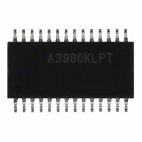
A3980KLPTR-T Allegro Microsystems Inc, A3980KLPTR-T Datasheet - Page 15

A3980KLPTR-T
Manufacturer Part Number
A3980KLPTR-T
Description
IC DRIVER MICROSTEPPING 28-TSSOP
Manufacturer
Allegro Microsystems Inc
Datasheet
1.A3980KLPTR-T.pdf
(18 pages)
Specifications of A3980KLPTR-T
Applications
Stepper Motor Driver
Number Of Outputs
1
Current - Output
± 1A
Voltage - Load
7 V ~ 50 V
Voltage - Supply
3 V ~ 5.5 V
Operating Temperature
-40°C ~ 125°C
Mounting Type
Surface Mount
Package / Case
28-TSSOP Exposed Pad, 28-eTSSOP, 28-HTSSOP
Motor Type
DMOS
No. Of Outputs
2
Output Current
1A
Output Voltage
50V
Supply Voltage Range
3V To 5.5V
Driver Case Style
TSSOP
No. Of Pins
28
Operating Temperature Range
-40°C To +125°C
Operating Current
12mA
Operating Temperature Classification
Automotive
Package Type
TSSOP EP
Operating Supply Voltage (min)
3V
Operating Supply Voltage (typ)
5V
Operating Supply Voltage (max)
5.5V
Lead Free Status / RoHS Status
Lead free / RoHS Compliant
Lead Free Status / RoHS Status
Lead free / RoHS Compliant, Lead free / RoHS Compliant
Other names
620-1298-2
A3980KLPTR-T
A3980KLPTR-T
Available stocks
Company
Part Number
Manufacturer
Quantity
Price
A3980
The total dissipation for each of the four decay modes is the
average power for the current ramp and the current decay
portions of the PWM cycle.
For slow decay, the current is rising for approximately 20%
of the cycle and decaying for approximately 80%. For fast
decay, the ratio is approximately 50% for each. Note that
these are approximate fi gures, and they vary slightly depend-
ing on the motor characteristics and the use of synchronous
rectifi cation.
The power dissipation, P
calculated as shown in the following formulas.
Synchronous slow decay mode:
Allowable Package Power Dissipation
5
4
3
2
1
0
P
1
“High-K” 4-layer PCB.
2
with 3 in.
TOT
25
R
R
θJA
θJA
= [0.2
at 28ºC/ W measured on a JEDEC-standard
at 38ºC/ W measured on a typical 2-sided PCB
2
2
(1935 mm
R
×
50
θJA
I
2
P
TOT
(R
= 38ºC/W
Ambient Temperature (°C)
DSONH
= (0.2
2
) copper ground area.
75
TOT
+ R
, in each decay mode can be
×
1
DSONL
R
P
D
θJA
) + (0.8
100
)] + [0.8
= 28ºC/W
×
×
125
P
SS
I
2
)
Automotive DMOS Microstepping Driver
(2
×
R
150
DSONL
)]
Non-synchronous slow decay mode:
Synchronous fast decay mode:
Non-synchronous fast decay mode:
An approximation of the total dissipation can be calculated
by summing the total power dissipated in both full-bridges
and adding the control circuit power due to V
V
ture can then be compared to the allowable power dissipation,
shown in the Allowable Package Power Dissipation chart.
For critical applications, where the fi rst order power estimate
is close to the allowable dissipation, the power calculation
should take several other parameters into account including:
motor parameters, dead time, and switching losses in the
controller.
Layout. The printed circuit board should use a heavy
ground plane. For optimum electrical and thermal perfor-
mance, the A3980 should be soldered directly onto the board.
The load supply terminal, V
an electrolytic capacitor (> 47 μF is recommended), placed
as close to the A3980 as possible. To avoid problems due to
capacitive coupling of the high dv/dt switching transients,
route the full-bridge output traces away from the sensitive
logic input traces. Always drive the logic inputs with a low
source impedance to increase noise immunity.
Grounding. A star ground system located close to the
A3980 is recommended. On the 28-lead TSSOP package, the
analog ground (lead 7) and the power ground (lead 21) must
be connected together externally. The copper ground plane
located under the exposed thermal pad is typically used as
the star ground point.
DD
P
P
×
TOT
TOT
I
DD
= [0.2
= [0.5
. The total power at the required ambient tempera-
×
×
I
2
P
P
(R
I
P
P
TOT
TOT
2
TOT
TOT
DSONH
(R
= (0.5
= (0.5
DSONH
= (0.2
= I
+ R
2
(R
115 Northeast Cutoff
1.508.853.5000; www.allegromicro.com
Allegro MicroSystems, Inc.
Worcester, Massachusetts 01615-0036 U.S.A.
DSONL
×
BB
×
×
+ R
DSONH
, should be decoupled with
P
P
P
D
D
DSONL
D
)] + {0.8
) + (0.8
) + (0.5
) + (0.5
with Translator
+ R
)] + (0.5
DSONL
×
×
×
×
[I
P
2
P
P
)
R
NS
NF
BB
SF
×
DSONL
)
)
)
I
×
2
×
+ (I
I
BB
R
×
DSONL
and
V
F
)]}
)
15


