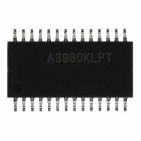
A3980KLPTR-T Allegro Microsystems Inc, A3980KLPTR-T Datasheet - Page 13

A3980KLPTR-T
Manufacturer Part Number
A3980KLPTR-T
Description
IC DRIVER MICROSTEPPING 28-TSSOP
Manufacturer
Allegro Microsystems Inc
Datasheet
1.A3980KLPTR-T.pdf
(18 pages)
Specifications of A3980KLPTR-T
Applications
Stepper Motor Driver
Number Of Outputs
1
Current - Output
± 1A
Voltage - Load
7 V ~ 50 V
Voltage - Supply
3 V ~ 5.5 V
Operating Temperature
-40°C ~ 125°C
Mounting Type
Surface Mount
Package / Case
28-TSSOP Exposed Pad, 28-eTSSOP, 28-HTSSOP
Motor Type
DMOS
No. Of Outputs
2
Output Current
1A
Output Voltage
50V
Supply Voltage Range
3V To 5.5V
Driver Case Style
TSSOP
No. Of Pins
28
Operating Temperature Range
-40°C To +125°C
Operating Current
12mA
Operating Temperature Classification
Automotive
Package Type
TSSOP EP
Operating Supply Voltage (min)
3V
Operating Supply Voltage (typ)
5V
Operating Supply Voltage (max)
5.5V
Lead Free Status / RoHS Status
Lead free / RoHS Compliant
Lead Free Status / RoHS Status
Lead free / RoHS Compliant, Lead free / RoHS Compliant
Other names
620-1298-2
A3980KLPTR-T
A3980KLPTR-T
Available stocks
Company
Part Number
Manufacturer
Quantity
Price
A3980
Shorted Load. A short across the load is detected by moni-
toring the voltage across both the top and bottom FETs in each
full-bridge.
Short Fault Operation. Because motor capacitance may
cause the measured voltages to show a fault as the full-bridge
switches, voltages are not sampled until after the blank time plus
an internally-generated delay, t
detected, all outputs for the faulty phase are disabled until the
next step command. At the next step command, the outputs are
re-enabled and the voltage across the FET is resampled.
While the fault persists, the A3980 continues this cycle at each
step command: enabling the outputs for a short period, and then
disabling the outputs. This allows the A3980 to handle a continu-
ous short circuit without damage. If, while stepping rapidly, a
short circuit appears and no action is taken, the repeated short-cir-
cuit current pulses eventually cause the temperature of the A3980
to rise and an overtemperature fault occurs.
Low Load Current Fault Operation. A low load current is
detected by monitoring the measured phase current in each output
while driving the motor in the Home microstep position. At the
Home microstep position, each phase current should reach 70%
of I
expected value (more than 35% of I
microstep position, then a low load current condition is reported
on the next rising edge of the STEP input. If the measured cur-
rent in both phases exceeds 35% of I
generated on the next rising edge of the STEP input.
If an open load condition appears while stepping, then it is
detected after the translator cycles through the Home state.
Although the A3980 continues to drive the DMOS outputs during
an open load condition, it does not clear the fault fl ags until the
next Home state occurs.
There are two conditions that can cause a low load current. The
fi rst is an open circuit on either or both motor phase connections.
In this condition, current can never fl ow through the phase so a
low load current will always be fl agged. The second condition is
where the back EMF of the motor limits the phase current to less
than the low load current trip level. This will happen when the
stepper motor is running close to its limiting speed. To confi rm an
open load condition when a low load current is fl agged, the step
rate should be reduced to a level below half the maximum step
rate. If the low load current fl ag remains active at the lower step
TripMax
. If either phase current does not exceed half of this
SCT
. Once a short circuit has been
TripMax
TripMax
) while in the Home
) then no fault will be
Automotive DMOS Microstepping Driver
rate, after completing the number of steps required to pass the
home condition, then an open circuit condition is confi rmed.
To allow immediate detection of an open load condition at power
up or after coming out of sleep mode, the A3980 translator is
reset to the Home microstep position and the low load current
fault fl ags are set. If no open load condition exists then the fault
fl ags will be reset on the next rising edge of the STEP input.
Supply Monitors.
tored to ensure that they are within the correct operating range.
If the main supply exceeds the overvoltage limit, V
fl ags are set and the A3980 enters a safety mode in which all low-
side DMOS FETs are enabled and all high-side DMOS FETs are
disabled. This allows the A3980 to survive a load dump transient
condition that has up to 50 V on VBATT and a duration of up
to 500 ms. If the internal regulator V
below their respective undervoltage limits (V
fault fl ags are set, the DMOS outputs are disabled, and the internal
logic is reset to the power-on state (the translator is set to the Home
state).
Diagnostic Fault Flags
ditions are reported using the two fault fl ag outputs (open drain).
These are active-low outputs which are coded as shown in table
2 to discriminate between the fault conditions. When both fault
fl ags are high, no fault exists.
External and internal supplies are moni-
115 Northeast Cutoff
1.508.853.5000; www.allegromicro.com
Allegro MicroSystems, Inc.
Worcester, Massachusetts 01615-0036 U.S.A.
(FF1, FF2)
REG
with Translator
or the logic supply V
UVR
.
Diagnostic fault con-
or V
UVD
OVB
), then: the
, the fault
DD
go
13


