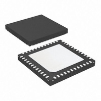
ATA6834-PLQW Atmel, ATA6834-PLQW Datasheet - Page 7

ATA6834-PLQW
Manufacturer Part Number
ATA6834-PLQW
Description
IC BLDC MOTOR DVR/LIN SBC 48VQFN
Manufacturer
Atmel
Type
3 Phase Brushless DC Motor Controllerr
Datasheet
1.ATA6833-PLQW.pdf
(27 pages)
Specifications of ATA6834-PLQW
Applications
DC Motor Controller, Brushless (BLDC), 3 Phase
Number Of Outputs
1
Voltage - Supply
5.5 V ~ 22.3 V
Operating Temperature
-40°C ~ 150°C
Mounting Type
Surface Mount
Package / Case
48-VQFN Exposed Pad, 48-HVQFN, 48-SQFN, 48-DHVQFN
Product
Fan / Motor Controllers / Drivers
Supply Current
7 mA
Mounting Style
SMD/SMT
Lead Free Status / RoHS Status
Lead free / RoHS Compliant
Current - Output
-
Voltage - Load
-
Lead Free Status / Rohs Status
Lead free / RoHS Compliant
3.3
Figure 3-2.
9122G–AUTO–10/10
4 0
3 0
2 0
3 5
2 5
5V/3.3V VCC Regulator
10
15
0
5
0
ESR versus Load Current for External Capacitors with Different Values
ESR versus Load Current at Pin VCC
2 5
ESR
ESR
Load Current (mA)
max
min
50
(C
(C
VCC
VCC
The 5V/3.3V regulator is fully integrated. It requires an external electrolytic capacitor in the
range of 2.2µF up to 10µF and with an ESR in the range from 2 to 15 for stability (see
ure
to either pin VINT or GND. Since the regulator is not designed to be switched between both
output voltages during operation, it is advisable to hard-wire VMODE pin. The logic levels of
the microcontroller interface are adapted to the VCC regulator output voltage. The maximum
output current (I
reduced to 80mA. The VCC regulator has a built-in short circuit protection. A comparator
checks the output voltage of the VCC regulator and keeps the external microcontroller in reset
as long as the voltage is below the lower operation minimum (shown in
Figure 3-3.
= 2.2µF)
= 2.2µF)
3-2). The output voltage can be configured as either 5V or 3.3V by connecting pin VMODE
75
10 0
/RESET as Function of the VCC Output Voltage
100% VCC
OS1
88% VCC
80% VCC
12 5
) of the regulator is 100mA. For T
Atmel ATA6833/ATA6834 [Preliminary]
/RESET
VCC
0V
150
2 0
2 5
10
15
0
5
0
ESR versus Load Current at Pin VCC
2 5
ESR
J
> 150°C the I
ESR
min
Load Current (mA)
(C
50
max
VCC
(C
= 10µF)
VCC
= 10µF)
75
OS1
Figure
10 0
of Atmel
3-3).
12 5
®
ATA6834 is
150
Fig-
7


