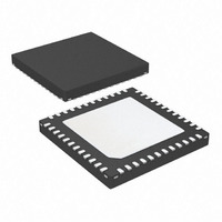
ATA6834-PLQW Atmel, ATA6834-PLQW Datasheet - Page 14

ATA6834-PLQW
Manufacturer Part Number
ATA6834-PLQW
Description
IC BLDC MOTOR DVR/LIN SBC 48VQFN
Manufacturer
Atmel
Type
3 Phase Brushless DC Motor Controllerr
Datasheet
1.ATA6833-PLQW.pdf
(27 pages)
Specifications of ATA6834-PLQW
Applications
DC Motor Controller, Brushless (BLDC), 3 Phase
Number Of Outputs
1
Voltage - Supply
5.5 V ~ 22.3 V
Operating Temperature
-40°C ~ 150°C
Mounting Type
Surface Mount
Package / Case
48-VQFN Exposed Pad, 48-HVQFN, 48-SQFN, 48-DHVQFN
Product
Fan / Motor Controllers / Drivers
Supply Current
7 mA
Mounting Style
SMD/SMT
Lead Free Status / RoHS Status
Lead free / RoHS Compliant
Current - Output
-
Voltage - Load
-
Lead Free Status / Rohs Status
Lead free / RoHS Compliant
4. Absolute Maximum Ratings
Stresses beyond those listed under “Absolute Maximum Ratings” may cause permanent damage to the device. This is a stress rating
only and functional operation of the device at these or any other conditions beyond those indicated in the operational sections of this
specification is not implied. Exposure to absolute maximum rating conditions for extended periods may affect device reliability.
All voltages are referenced to pin GND. (xxx) Values for the Atmel
5. Thermal Resistance
14
Parameters
Input voltage
Negative input current
Negative input current
Supply voltage
Supply voltage
Logic output voltage
Logic input voltage
Output voltage
Analog input voltage
Digital input voltage
Digital input voltage
Output voltage
Input voltage
Output voltage
Output voltage
Output voltage
Charge pump
Charge pump
Output voltage
Output voltage
Storage temperature
Note:
Parameters
Thermal resistance junction to heat slug
Thermal resistance junction to ambient when heat slug
is soldered to PCB
Estimated values take T
Atmel ATA6833/ATA6834 [Preliminary]
J
> 150°C into account.
IL1-3, IH1-3, WD,
WDD, EN1, TXD
DG2, DG3, RXD
/RESET, DG1,
VINT, VCC
S1, S2, S3
H1, H2, L3
L1, L2, L3
CPLO1, 2
RWD, CC
VBATSW
CPHI1, 2
VMODE
CPOUT
PGND
VBAT
PBAT
VBAT
PBAT
EN2
Pin
LIN
VG
V
V
/RESET
IL1-3
V
V
V
V
V
CPLO1
CPHO1
V
V
V
®
H1
S1
L1
Symbol
INT
V
DG3
, V
EN1
V
V
T
Symbol
ATA6834.
IVBAT
IPBAT
V
, V
, V
, V
, V
V
V
V
V
VBATSW
V
VMODE
Storage
V
CPOUT
, V
PGND
R
R
VBAT
PBAT
RWD
VLIN
IH1-3
EN2
, V
, V
, V
VG
H2
, V
DG1
S2
L2
thjc
thja
VVCC
, V
, V
, V
RXD
TXD
CPLO2
CPHO2
, V
, V
S3
L3
H3
WD
DG2
,
,
V
V
PGND
S1, 2, 3
Min.
–0.3
–0.3
–0.3
–0.3
–0.3
–0.3
–0.3
–0.3
–0.3
–0.3
–0.3
–0.3
–0.3
–0.3
–15
–20
–27
–55
–6
– 0.3
– 1
Value
< 5
25
V
V
V
V
V
V
V
V
V
CPOUT
V
V
S1, 2, 3
VBAT
PBAT
VBAT
VINT
VCC
VCC
VCC
VBAT
VG
Max.
+150
+0.3
+5.5
+40
+40
+16
+30
+40
+ 0.3
+ 0.3
+ 0.3
+ 0.3
+ 0.3
+ 0.3
+ 0.3
+ 0.3
+ 0.3
+ 2
+ 16
9122G–AUTO–10/10
Unit
Unit
K/W
K/W
mA
mA
°C
V
V
V
V
V
V
V
V
V
V
V
V
V
V
V
V
V
V


