L6219R STMicroelectronics, L6219R Datasheet - Page 8
L6219R
Manufacturer Part Number
L6219R
Description
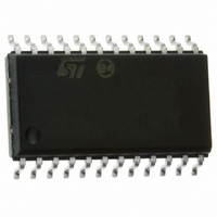
IC STEPPER MOTOR DRIVER SO-24
Manufacturer
STMicroelectronics
Type
Driverr
Datasheet
1.E-L6219R013TR.pdf
(16 pages)
Specifications of L6219R
Applications
DC Motor Driver, Stepper Motor Driver
Number Of Outputs
2/1
Current - Output
±500mA
Voltage - Load
4.5 V ~ 10 V
Voltage - Supply
4.75 V ~ 5.25 V
Operating Temperature
-20°C ~ 85°C
Mounting Type
Surface Mount
Package / Case
24-SOIC (7.5mm Width)
Product
Stepper Motor Controllers / Drivers
Operating Supply Voltage
4.5 V to 30 V
Supply Current
0.01 A
Mounting Style
SMD/SMT
Lead Free Status / RoHS Status
Lead free / RoHS Compliant
Available stocks
Company
Part Number
Manufacturer
Quantity
Price

Company:
Part Number:
L6219R013TR
Manufacturer:
SONY
Quantity:
6 219


Electrical specifications
2.3
Table 5.
1. The maximum reference voltage accepted by the device depends from the supply voltage Vs (see
2. To reduce the switching losses the base bias of the bridge's low side NPN transistor is proportional to the DAC output, then
8/16
OUTPUT DRIVERS (OUT
CONTROL LOGIC
COMPARATORS
PROTECTION
Symbol
I
V
I
SS(OFF)
V
V
SS(ON)
V
V
V
I
I
I
I
I
CE(sat)
S(on)
S(off)
the output current driving capability is also proportional to the DAC output voltage (see
DAC=100%, it is proportional for lower percentages).
IN(H)
IN(L)
CEX
sense
V
V
IN(H)
t
IN(L)
REF
T
REF
t
off
d
S
F
J
/
Motor supply range
Output leakage current
Output saturation voltage
Clamp diode forward voltage
Driver supply current
Driver supply current
Input voltage
Input voltage
Input current
Input current
Reference voltage
Total logic supply current
Total logic supply current
Current limit threshold (at trip
point)
Cutoff time
Turn off delay
Thermal shutdown temperature
Electrical characteristics
Electrical characteristics
(T
See
.
j
= 25 °C, V
Figure
Parameter
A
5.
or OUT
S
= 4.5 V, V
B
)
SS
= 4.75 V to 5.25 V, V
Source driver, I
Source driver, I
Both bridges OFF, V
Sink driver, I
Sink driver, I
Source diode I
Both bridges ON, no load
R
I
I
V
o
o
I
I
t
V
o
o
s
= I
= I
= 56 KΩ C
s
Test Condition
Operating
= 2.4 V, I
= 0.8 V, I
= 30 V, V
= 30 V, V
I
1
1
see
V
o
V
Sink diode
V
All inputs
All inputs
IN
= 0.8 V, no load
= 2.4 V, no load
= I
IN
s
= 0.84 V
1
Figure 1
= 10 V
= 2.4 V
OUT
OUT
= 0.8 V
OUT
OUT
1
1
OUT
t
F
OUT
= +300 mA
= 820 pF
= +500 mA
(1) (2)
= 0.8 V
= 2.4 V
= 500 mA
= -300 mA
= -500 mA
REF
= V
s
= 0
= 10 V
s
= 2 V, unless otherwise specified)
,
Figure 6
Min.
13.5
25.5
4.5
-50
2.4
1.5
9.5
-
-
-
-
-
-
-
-
-
-
-
-
-
-
-
and
Figure
Typ.
170
<-1
0.3
0.7
1.1
1.3
<1
<1
44
10
10
15
30
50
-3
Figure 8
1
1
8
6
1
-
-
-
7).
Max.
-200
10.5
16.5
34.5
for
0.6
1.4
1.6
1.5
1.5
0.8
50
15
20
10
10
60
14
1
2
-
-
L6219R
Unit
mA
mA
mA
mA
μA
μA
μA
μA
°C
μs
μs
V
V
V
V
V
V
V
V
V
V
-
-
-
Related parts for L6219R
Image
Part Number
Description
Manufacturer
Datasheet
Request
R

Part Number:
Description:
IC, MOTOR DRIVER, STEPPER, 750mA, DIP-24
Manufacturer:
STMicroelectronics
Datasheet:
Part Number:
Description:
STMicroelectronics [RIPPLE-CARRY BINARY COUNTER/DIVIDERS]
Manufacturer:
STMicroelectronics
Datasheet:
Part Number:
Description:
STMicroelectronics [LIQUID-CRYSTAL DISPLAY DRIVERS]
Manufacturer:
STMicroelectronics
Datasheet:

Part Number:
Description:
BOARD EVAL FOR MEMS SENSORS
Manufacturer:
STMicroelectronics
Datasheet:
Part Number:
Description:
NPN TRANSISTOR POWER MODULE
Manufacturer:
STMicroelectronics
Datasheet:
Part Number:
Description:
TURBOSWITCH ULTRA-FAST HIGH VOLTAGE DIODE
Manufacturer:
STMicroelectronics
Datasheet:
Part Number:
Description:
Manufacturer:
STMicroelectronics
Datasheet:
Part Number:
Description:
DIODE / SCR MODULE
Manufacturer:
STMicroelectronics
Datasheet:
Part Number:
Description:
DIODE / SCR MODULE
Manufacturer:
STMicroelectronics
Datasheet:
Part Number:
Description:
Search -----> STE16N100
Manufacturer:
STMicroelectronics
Datasheet:
Part Number:
Description:
Search ---> STE53NA50
Manufacturer:
STMicroelectronics
Datasheet:
Part Number:
Description:
NPN Transistor Power Module
Manufacturer:
STMicroelectronics
Datasheet: