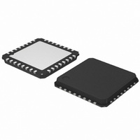
AMIS30624C6245RG ON Semiconductor, AMIS30624C6245RG Datasheet - Page 37

AMIS30624C6245RG
Manufacturer Part Number
AMIS30624C6245RG
Description
IC STEPPER DVR I2C 800MA 32-NQFP
Manufacturer
ON Semiconductor
Type
I2C Micro Stepping Motor Driverr
Datasheet
1.AMIS30624C6244RG.pdf
(56 pages)
Specifications of AMIS30624C6245RG
Applications
Stepper Motor Driver, 2 Phase
Number Of Outputs
1
Current - Output
800mA
Voltage - Supply
8 V ~ 29 V
Operating Temperature
-40°C ~ 165°C
Mounting Type
Surface Mount
Package / Case
32-VSQFP
Product
Stepper Motor Controllers / Drivers
Operating Supply Voltage
8 V to 29 V
Supply Current
800 mA
Mounting Style
SMD/SMT
Lead Free Status / RoHS Status
Lead free / RoHS Compliant
Voltage - Load
-
Lead Free Status / Rohs Status
Lead free / RoHS Compliant
Other names
766-1002-2
Available stocks
Company
Part Number
Manufacturer
Quantity
Price
Company:
Part Number:
AMIS30624C6245RG
Manufacturer:
ON Semiconductor
Quantity:
212
Company:
Part Number:
AMIS30624C6245RG
Manufacturer:
ON Semiconductor
Quantity:
1 850
Company:
Part Number:
AMIS30624C6245RG
Manufacturer:
ON Semiconductor
Quantity:
10 000
AMIS-30624
15.0 I
15.1 General Description
AMIS-30624 uses a simple bi-directional 2-wire bus for efficient inter-ic control. This bus is called the Inter IC or I
Features include:
15.2 Concept
The I
bus. Each device connected to the bus is recognized by a unique address and operates as either a transmitter or receiver, depending
on the function of the device. AMIS-30624 can both receive and transmit data. In addition to transmitters and receivers, devices can
also be considered as masters or slaves when performing data transfers. AMIS-30624 is a slave device. See Table 30.
Table 29: Definition of I
Transmitter
Receiver
Master
Slave
Synchronization
Figure 23 highlights the master-slave and receiver-transmitter relationships to be found on the I
relationships are not permanent but only depend on the direction of data transfer at that time. The transfer of data would proceed as
follows:
1) Suppose the microcontroller wants to send information to motordriver_1:
2
C-bus consists of two wires, serial data (SDA) and serial clock (SCK), carrying information between the devices connected on the
• Only two bus lines are required; a serial data line (SDA) and a serial clock line (SCK).
• Each device connected to the bus is software addressable by a unique address and simple master/slave relationships exists at
• Serial, 8-bit oriented, bi-directional data transfers can be made up to 400 kbit/s.
• On-chip filtering rejects spikes on the bus data line to preserve data integrity.
• No need to design bus interfaces because I
• IC’s can be added to or removed from a system without affecting any other circuits on the bus.
• Microcontroller (master) addresses motordriver_1 (slave)
• Microcontroller (master-transmitter) sends data to motordriver_1 (slave-receiver)
• Microcontroller terminates the transfer
2
all times; master can operate as master-transmitter or as master receiver.
C Bus Description
Term
2
C –bus Terminology
SDA
SCL
The device which sends data on the bus
The device which receives data from the bus
The device which initiates a transfer, generates clock signals and terminates a transfer
The devices addressed by a master
Procedure to synchronizer the clock signals of two or more devices
Figure 23: Example of an I
controller
Micro-
Motordriver_1
AMIS-30624
Rev. 4 | Page 37 of 56 | www.onsemi.com
2
2
C-bus Configuration Using One Microcontroller and Four Slaves
C-bus interface is already integrated on-chip.
Motordriver_2
AMIS-30624
Description
Motordriver_3
AMIS-30624
Motordriver_4
AMIS-30624
2
C-bus. It should be noted that these
PC20070217.1
2
C-bus.


