VN340SP-E STMicroelectronics, VN340SP-E Datasheet
VN340SP-E
Specifications of VN340SP-E
Available stocks


Related parts for VN340SP-E


VN340SP-E Summary of contents
Page 1
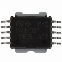
... I CC out 0.7A 36V Description The VN340SP monolithic device made using STMicroelectronics VIPower technology, intended for driving four indipendent resistive or inductive loads with one side connected to ground. Active current limitation avoids dropping the system power supply in case of shorted load. Built-in thermal shut-down protects the chip from overtemperature and short circuit ...
Page 2
... Contents Contents 1 Maximum ratings . . . . . . . . . . . . . . . . . . . . . . . . . . . . . . . . . . . . . . . . . . . . . . 3 2 Pin connections . . . . . . . . . . . . . . . . . . . . . . . . . . . . . . . . . . . . . . . . . . . . . . 4 3 Electrical characteristics . . . . . . . . . . . . . . . . . . . . . . . . . . . . . . . . . . . . . . . 5 4 Test circuits . . . . . . . . . . . . . . . . . . . . . . . . . . . . . . . . . . . . . . . . . . . . . . . . . . 7 5 Switching time waveforms and truth table . . . . . . . . . . . . . . . . . . . . . . . . . 9 6 Package mechanical data . . . . . . . . . . . . . . . . . . . . . . . . . . . . . . . . . . . . . . 11 7 Order code . . . . . . . . . . . . . . . . . . . . . . . . . . . . . . . . . . . . . . . . . . . . . . . . . . 14 8 Revision history . . . . . . . . . . . . . . . . . . . . . . . . . . . . . . . . . . . . . . . . . . . . . 15 2/16 VN340SP-E ...
Page 3
... VN340SP-E 1 Maximum ratings Table 1. Absolute maximum rating Symbol V Power supply voltage CC -V Reverse supply voltage CC I Output current (continuos) OUT I Reverse output current (per channel Input current (per channel Diag pin current DIAG V Electrostatic discharge (R = 1.5KΩ 100pF) ESD Single pulse avalanche energy per channel not simultaneously ...
Page 4
... Connection diagram (top view) Figure 3. Current and voltage conventions IN1 V IN2 V IN3 V IN4 4/16 I IN1 IN1 I IN2 9 IN2 1 OUT1 I IN3 8 IN3 OUT2 I IN4 IN4 7 OUT3 3 I DIAG 6 DIAG OUT4 GND V DIAG 5 VN340SP-E I OUT1 V OUT1 I OUT2 2 V OUT2 I OUT3 V OUT3 I OUT4 4 V OUT4 ...
Page 5
... VN340SP-E 3 Electrical characteristics 10V < V < 36V; -40°C < Table 3. Power section Symbol Parameter V Supply voltage state resistance ON I Supply current S V Low state output voltage Output voltage at turn-off I demag I Output current at turn-off LGND Table 4. Switching ( V = 24V) CC Symbol Parameter Turn-on delay time of t d(ON) ...
Page 6
... Test conditions = 5mA ( Fault condition ) DIAG I = 1mA DIAG I = 1mA DIAG V = 24V; R < 10mΩ CC LOAD = 24V 30; R < 10mΩ LOAD V = 24V DIAG 36V VN340SP-E Min Typ Max -0 0 100 150 170 135 155 not exceed 36V. Unit µΑ µΑ ...
Page 7
... VN340SP-E 4 Test circuits Figure 4. Avalance energy test circuit Figure 5. Peak short circuit test diagram Test circuits 7/16 ...
Page 8
... Test circuits Figure 6. I test configuration LGND 8/16 VN340SP-E ...
Page 9
... VN340SP-E 5 Switching time waveforms and truth table Figure 7. Switching waveforms Figure 8. Switching parameter test conditions Switching time waveforms and truth table 9/16 ...
Page 10
... Switching time waveforms and truth table Table 7. Truth table Normal operation Overtemperature Undervoltage Shorted load ( Current limitation ) Figure 9. Driving circuit 10/16 MCOUTn I/ VN340SP-E OUTPUTn Diagnostic ...
Page 11
... VN340SP-E 6 Package mechanical data In order to meet environmental requirements, ST offers these devices in ECOPACK® packages. These packages have a Lead-free second level interconnect . The category of second level interconnect is marked on the package and on the inner box label, in compliance with JEDEC Standard JESD97. The maximum ratings related to soldering conditions are also marked on the inner box label ...
Page 12
... VN340SP-E Inch Typ Max 0.144 0.004 0.024 0.012 0.378 0.300 0.374 0.291 0.300 0.250 0.240 0.050 0.053 0.567 0.002 0.071 0.067 ...
Page 13
... VN340SP-E TM Figure 11. PowerSO-10 Suggested Pad and Tube Shipment (No Suffix) Figure 12. Tape and Reel Shipment (Suffix “TR“) Package mechanical data 13/16 ...
Page 14
... Order code 7 Order code Table 9. Order code Part number VN340SP-E VN340SPTR-E 14/16 Package TM PowerSO-10 TM PowerSO-10 VN340SP-E Packaging Tube Tape and reel ...
Page 15
... VN340SP-E 8 Revision history Table 10. Revision history Date Revision 5-Sep-2005 1 27-Jun-2006 2 18-Sep-2006 3 31-Oct-2006 4 05-Mar-2007 5 Changes Initial release Mechanical data updated Mechanical data updated, Added powerSO-10 Tape and reel information Typo in Electrical characteristics temperature conditions updated Document reformatted, typo in Note 1 on page 6 Revision history ...
Page 16
... Australia - Belgium - Brazil - Canada - China - Czech Republic - Finland - France - Germany - Hong Kong - India - Israel - Italy - Japan - Malaysia - Malta - Morocco - Singapore - Spain - Sweden - Switzerland - United Kingdom - United States of America 16/16 Please Read Carefully: © 2007 STMicroelectronics - All rights reserved STMicroelectronics group of companies www.st.com VN340SP-E ...