VN05N STMicroelectronics, VN05N Datasheet - Page 12
VN05N
Manufacturer Part Number
VN05N
Description
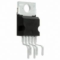
RELAY SSR HI-SIDE 5-PENTAWATT
Manufacturer
STMicroelectronics
Type
High Sider
Datasheet
1.VN05N-E.pdf
(16 pages)
Specifications of VN05N
Input Type
Non-Inverting
Number Of Outputs
1
On-state Resistance
360 mOhm
Current - Output / Channel
13A
Current - Peak Output
60A
Voltage - Supply
7 V ~ 26 V
Operating Temperature
-40°C ~ 150°C
Mounting Type
Through Hole
Package / Case
Pentawatt-5 (Vertical, Bent and Staggered Leads)
Supply Voltage (min)
7 V
Supply Current
15 mA
Maximum Power Dissipation
56000 mW
Maximum Operating Temperature
+ 150 C
Mounting Style
Through Hole
Minimum Operating Temperature
- 40 C
Lead Free Status / RoHS Status
Contains lead / RoHS non-compliant
Other names
497-3088-5
Available stocks
Company
Part Number
Manufacturer
Quantity
Price

Company:
Part Number:
VN05N-E
Manufacturer:
LUMEX
Quantity:
20 000
Company:
Part Number:
VN05NSP
Manufacturer:
INFINEON
Quantity:
101
Part Number:
VN05NSP
Manufacturer:
ST
Quantity:
20 000


Application information
3.1
3.2
12/16
Functional description
The device has a diagnostic output which indicates open circuit (no load) and over
temperature conditions. The output signals are processed by internal logic. To protect the
device against short circuit and over-current condition, the thermal protection turns the
integrated Power MOS off at a minimum junction temperature of 140°C. When the
temperature returns to about 125°C the switch is automatically turned on again. In short
circuit conditions the protection reacts with virtually no delay, the sensor being located in the
region of the die where the heat is generated.
Protecting the device against reverse battery
The simplest way to protect the device against a continuous reverse battery voltage (-26V)
is to insert a Schottky diode between pin 1 (GND) and ground, as shown in the typical
application circuit
The consequences of the voltage drop across this diode are as follows:
●
●
If there is no need for the control unit to handle external analog signals referred to the power
GND, the best approach is to connect the reference potential of the control unit to node [1]
(see
this way no shift of V
INPUT pin; this solution allows the use of a standard diode, with a breakdown voltage able
to handle any ISO normalized negative pulses that occours in the automotive environment.
If the input is pulled to power GND, a negative voltage of -V
V
The undervoltage shutdown level is increased by V
Figure
IH
thresholds and V
13.), which becomes the common signal GND for the whole control board. In
(Figure
IH
, V
IL
STAT
12.).
and V
are increased by V
STAT
takes place and no negative voltage appears on the
F
with respect to power GND).
F
.
F
is seen by the device. (V
VN05N
IL
,
Related parts for VN05N
Image
Part Number
Description
Manufacturer
Datasheet
Request
R

Part Number:
Description:
HIGH SIDE SMART POWER SOLID STATE RELAY
Manufacturer:
STMicroelectronics
Datasheet:
Part Number:
Description:
STMicroelectronics [RIPPLE-CARRY BINARY COUNTER/DIVIDERS]
Manufacturer:
STMicroelectronics
Datasheet:
Part Number:
Description:
STMicroelectronics [LIQUID-CRYSTAL DISPLAY DRIVERS]
Manufacturer:
STMicroelectronics
Datasheet:

Part Number:
Description:
BOARD EVAL FOR MEMS SENSORS
Manufacturer:
STMicroelectronics
Datasheet:
Part Number:
Description:
NPN TRANSISTOR POWER MODULE
Manufacturer:
STMicroelectronics
Datasheet:
Part Number:
Description:
TURBOSWITCH ULTRA-FAST HIGH VOLTAGE DIODE
Manufacturer:
STMicroelectronics
Datasheet:
Part Number:
Description:
Manufacturer:
STMicroelectronics
Datasheet:
Part Number:
Description:
DIODE / SCR MODULE
Manufacturer:
STMicroelectronics
Datasheet:
Part Number:
Description:
DIODE / SCR MODULE
Manufacturer:
STMicroelectronics
Datasheet:
Part Number:
Description:
Search -----> STE16N100
Manufacturer:
STMicroelectronics
Datasheet:
Part Number:
Description:
Search ---> STE53NA50
Manufacturer:
STMicroelectronics
Datasheet:
Part Number:
Description:
NPN Transistor Power Module
Manufacturer:
STMicroelectronics
Datasheet: