BTS410E2 Infineon Technologies, BTS410E2 Datasheet - Page 2
BTS410E2
Manufacturer Part Number
BTS410E2
Description
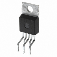
IC SWITCH PWR 65V TO-220AB-5
Manufacturer
Infineon Technologies
Series
PROFET®r
Type
High Sider
Datasheet
1.BTS410E2_E3062A.pdf
(16 pages)
Specifications of BTS410E2
Input Type
Non-Inverting
Number Of Outputs
1
On-state Resistance
190 mOhm
Current - Output / Channel
1.8A
Current - Peak Output
12A
Voltage - Supply
4.7 V ~ 42 V
Operating Temperature
-40°C ~ 150°C
Mounting Type
Through Hole
Package / Case
TO-220-5 (Bent and Staggered Leads)
Device Type
High Side
Peak Output Current
1.8A
Input Delay
125µs
Output Delay
85µs
Supply Voltage Range
4.7V To 42V
Driver Case Style
TO-220AB
No. Of Pins
5
Operating Temperature Range
-40°C
Switch Type
High Side
Power Switch Family
BTS 410 E2
Input Voltage
-0.5 to 6V
Power Switch On Resistance
190mOhm
Output Current
1.6A
Mounting
Through Hole
Supply Current
1mA
Package Type
TO-220AB
Operating Temperature (min)
-40C
Operating Temperature (max)
150C
Operating Temperature Classification
Automotive
Pin Count
5 +Tab
Power Dissipation
50W
Rohs Compliant
No
Output Resistance
0.19ohm
Lead Free Status / RoHS Status
Contains lead / RoHS non-compliant
Lead Free Status / RoHS Status
Contains lead / RoHS non-compliant, Contains lead / RoHS non-compliant
Other names
BTS410E2
BTS410E2IN
BTS410E2NK
SP000011233
BTS410E2IN
BTS410E2NK
SP000011233
Available stocks
Company
Part Number
Manufacturer
Quantity
Price
Company:

Part Number:
BTS410E2
Manufacturer:
INFINEON
Quantity:
6 500
Company:
Part Number:
BTS410E2
Manufacturer:
INF
Quantity:
5 510
Part Number:
BTS410E2
Manufacturer:
INFINEON/英飞凌
Quantity:
20 000
Part Number:
BTS410E2 E3062A
Manufacturer:
INFINEON/英飞凌
Quantity:
20 000
Company:
Part Number:
BTS410E2NKSA1
Manufacturer:
MICRON
Quantity:
1 400


Maximum Ratings at T
Parameter
Supply voltage (overvoltage protection see page 3)
Load dump protection
Load current (Short circuit current, see page 4)
Operating temperature range
Storage temperature range
Power dissipation (DC), T
Inductive load switch-off energy dissipation, single pulse
Electrostatic discharge capability (ESD)
Input voltage (DC)
Current through input pin (DC)
Current through status pin (DC)
see internal circuit diagrams page 6
Thermal Characteristics
Parameter and Conditions
Thermal resistance
2
3)
4)
5
Semiconductor Group
)
)
R
V
(Human Body Model)
acc. MIL-STD883D, method 3015.7 and ESD assn. std. S5.1-1993
Pin
1
2
3
4
5
bb
I
3
Supply voltages higher than V
150
protection of the input is integrated.
R
V
Device on 50mm*50mm*1.5mm epoxy PCB FR4 with 6cm
connection. PCB is vertical without blown air.
)
= 2
Load dump
I
= 12V, T
= internal resistance of the load dump test pulse generator
resistor in the GND connection and a 15 k
, R
is setup without the DUT connected to the generator per ISO 7637-1 and DIN 40839
L
j,start
Symbol
GND
IN
V bb
ST
OUT
(Load, L)
= 6.6
= 150°C, T
SMD version, device on PCB
, t
2
)
junction - ambient (free air):
d
V
= 400 ms, IN= low or high
j
= 25 °C unless otherwise specified
LoadDump
-
I
+
S
O
C
C
bb(AZ)
25 °C
= 150°C const.
Function
Logic ground
Input, activates the power switch in case of logical high signal
Positive power supply voltage,
the tab is shorted to this pin
Diagnostic feedback, low on failure
Output to the load
I
L
= 1.8 A, Z
require an external current limit for the GND and status pins, e.g. with a
= U
A
+ V
chip - case:
L
s
, U
= 2.3 H, 0
all other pins:
2
resistor in series with the status pin. A resistor for the
A
= 13.5 V
5)
:
2
(one layer, 70 m thick) copper area for V bb
R
R
Symbol
thJA
IN:
thJC
:
V
V
I
T
T
P
E
V
V
I
I
Symbol
L
IN
ST
Load dump
j
stg
bb
tot
AS
ESD
IN
min
4
)
--
--
--
Values
-40 ...+150
-55 ...+150
self-limited
typ
Values
35
-0.5 ... +6
--
--
BTS 410 E2
2003-Oct-01
100
max
4.5
5.0
5.0
2.5
65
50
75
1
2
--
Unit
Unit
K/W
mA
kV
°C
W
V
V
A
V
J
Related parts for BTS410E2
Image
Part Number
Description
Manufacturer
Datasheet
Request
R

Part Number:
Description:
Manufacturer:
Infineon Technologies
Datasheet:

Part Number:
Description:
Manufacturer:
Infineon Technologies AG
Datasheet:
Part Number:
Description:
Manufacturer:
Infineon Technologies AG
Datasheet:
Part Number:
Description:
Manufacturer:
Infineon Technologies AG
Datasheet:
Part Number:
Description:
Manufacturer:
Infineon Technologies AG
Datasheet:
Part Number:
Description:
Manufacturer:
Infineon Technologies AG
Datasheet:
Part Number:
Description:
Manufacturer:
Infineon Technologies AG
Datasheet:
Part Number:
Description:
Manufacturer:
Infineon Technologies AG
Datasheet:
Part Number:
Description:
16-bit microcontroller with 2x2 KByte RAM
Manufacturer:
Infineon Technologies AG
Datasheet:
Part Number:
Description:
NPN silicon RF transistor
Manufacturer:
Infineon Technologies AG
Datasheet:
Part Number:
Description:
NPN silicon RF transistor
Manufacturer:
Infineon Technologies AG
Datasheet:
Part Number:
Description:
NPN silicon RF transistor
Manufacturer:
Infineon Technologies AG
Datasheet:
Part Number:
Description:
NPN silicon RF transistor
Manufacturer:
Infineon Technologies AG
Datasheet:
Part Number:
Description:
Si-MMIC-amplifier in SIEGET 25-technologie
Manufacturer:
Infineon Technologies AG
Datasheet:
Part Number:
Description:
IGBT Power Module
Manufacturer:
Infineon Technologies AG
Datasheet: