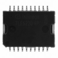
TLE6220GP Infineon Technologies, TLE6220GP Datasheet - Page 11

TLE6220GP
Manufacturer Part Number
TLE6220GP
Description
IC SW SMART QUAD LOSIDE DSO-20
Manufacturer
Infineon Technologies
Type
Low Sider
Datasheet
1.TLE6220GP.pdf
(19 pages)
Specifications of TLE6220GP
Input Type
SPI
Number Of Outputs
4
On-state Resistance
320 mOhm
Current - Output / Channel
3A
Current - Peak Output
6A
Voltage - Supply
4.5 V ~ 5.5 V
Operating Temperature
-40°C ~ 150°C
Mounting Type
Surface Mount
Package / Case
DSO-20
Switch Type
Low Side
Power Switch Family
TLE6220GP
Input Voltage
-0.3 to 7V
Power Switch On Resistance
320mOhm
Output Current
3A
Mounting
Surface Mount
Supply Current
1mA
Package Type
DSO
Operating Temperature (min)
-40C
Operating Temperature (max)
150C
Operating Temperature Classification
Automotive
Pin Count
22
Power Dissipation
3W
Packages
PG-DSO-20
Thermal Class
Heatslug down
Id Nom
4 x 1 A
Channels
4.0
Comment
inductive and resistive loads (e.g. injectors)
Lead Free Status / RoHS Status
Lead free / RoHS Compliant
Other names
SP000011903
SP000308873
TLE6220GPINTR
TLE6220GPNT
TLE6220GPT
TLE6220GPT
TLE6220GPXT
SP000308873
TLE6220GPINTR
TLE6220GPNT
TLE6220GPT
TLE6220GPT
TLE6220GPXT
Available stocks
Company
Part Number
Manufacturer
Quantity
Price
Company:
Part Number:
TLE6220GP
Manufacturer:
INFINEON
Quantity:
7 154
Company:
Part Number:
TLE6220GP
Manufacturer:
INFINEON
Quantity:
703
Part Number:
TLE6220GP
Manufacturer:
INFINEON/英飞凌
Quantity:
20 000
Part Number:
TLE6220GPAUMA2
Manufacturer:
INFINEON/英飞凌
Quantity:
20 000
Diagnostics
tion as soon as an error occurs for any one of the four channels. This fault indication can be
used to generate a µC interrupt. Therefore a ‘diagnosis’ interrupt routine need only be called
after this fault indication. This saves processor time compared to a cyclic reading of the SO
information.
As soon as a fault occurs, the fault information is latched into the diagnosis register. A new
error will over-write the old error report. Serial data out pin (SO) is in a high impedance state
when CS is high. If CS receives a LOW signal, all diagnosis bits can be shifted out serially.
The rising edge of CS will reset all error registers.
Full Diagnosis
For full diagnosis there are two diagnostic bits per channel configured as shown in Figure 1.
Normal function: The bit combination HH indicates that there is no fault condition, i.e. normal
function.
Overload, Short Circuit to Battery (SCB) or Overtemperature: HL is set when the current
limitation gets active, i.e. there is a overload, short to supply or overtemperature condition.
Open load: An open load condition is detected when the drain voltage decreases below 3 V
(typ.). LH bit combination is set.
Short Circuit to GND: If a drain to ground short circuit exists and the drain to ground current
exceeds 100 µA, short to ground is detected and the LL bit combination is set.
A definite distinction between open load and short to ground is guaranteed by design.
The standard way of obtaining diagnostic information is as follows:
Clock in serial information into SI pin and wait approximately 150 µs to allow the outputs to
settle. Clock in the identical serial information once again - during this process the data com-
ing out at SO contains the bit combinations representing the diagnosis conditions as de-
scribed in Figure 1.
V2.2
FAULT
Figure 1: Two bits per channel diagnostic feedback
Diagnostic Serial OUT (SO)
HH
HL
LH
LL
- Fault pin. There is a general fault pin (open drain) which shows a high to low transi-
7
Ch.4
6
Normal function
Overload, Shorted Load or Overtemperature
Open Load
Shorted to Ground
5
Ch.3
4
Ch.2
3
2
1
Ch.1
0
Page
11
Data Sheet TLE 6220 GP
2009-11-18


