MC33888FB Freescale Semiconductor, MC33888FB Datasheet - Page 18
MC33888FB
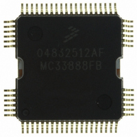
Manufacturer Part Number
MC33888FB
Description
IC SWITCH QUAD H-SIDE W/CS 64QFP
Manufacturer
Freescale Semiconductor
Type
High Side/Low Side Driverr
Datasheet
1.MC33888FBR2.pdf
(40 pages)
Specifications of MC33888FB
Input Type
SPI
Number Of Outputs
12 ( 4 High Side, 8 Low Side)
On-state Resistance
40 mOhm
Current - Output / Channel
10A
Current - Peak Output
60A
Voltage - Supply
6 V ~ 27 V
Operating Temperature
-40°C ~ 125°C
Mounting Type
Surface Mount
Package / Case
64-QFP
Lead Free Status / RoHS Status
Lead free / RoHS Compliant
Available stocks
Company
Part Number
Manufacturer
Quantity
Price
Company:

Part Number:
MC33888FB
Manufacturer:
GPS
Quantity:
6 218
Company:
Part Number:
MC33888FB
Manufacturer:
Freescale Semiconductor
Quantity:
10 000
Part Number:
MC33888FB
Manufacturer:
MOTOROLA/摩托罗拉
Quantity:
20 000
Company:
Part Number:
MC33888FBR2
Manufacturer:
Freescale Semiconductor
Quantity:
10 000
Part Number:
MC33888FBR2
Manufacturer:
FREESCALE
Quantity:
20 000


with four discrete high-side MOSFETs and an integrated IC
control die consisting of eight low-side drivers with
appropriate control, protection, and diagnostic features. The
high-side drivers are useful for both internal and external
vehicle lighting applications as well as capable of driving
inductive solenoid loads. The low-side drivers are capable of
controlling low-current on/off type inductive loads, such as
relays and solenoids as well as LED indicators and small
lamps (see
FAULT STATUS (FS)
low when a fault mode is detected by the device. Specific
device fault indication is given via the SO pin.
POSITIVE POWER SUPPLY (V
the source input of operational power for the device.
LOW-SIDE OUTPUT (LS4, LS6, LS8, LS10)
drain, which pulls current through the connected loads. Each
of the outputs is actively clamped at 53 V. These outputs are
current and thermal overload protected. Maximum steady
state current through each of these outputs is 500 mA.
GROUND (GND)
side output transistors as well as the logic portion of the
device.
LOW-SIDE OUTPUT (LS5, LS7, LS9, LS11)
drain, which pulls current through the connected loads. Each
of the outputs is actively clamped at 53 V. These outputs are
current and thermal overload protected. Maximum steady
state current through each of these outputs is 800 mA.
DIGITAL DRAIN VOLTAGE (V
SPI circuit.
SERIAL OUTPUT (SO)
pin of the MCU or to the SI pin of the next device in a daisy
chain. This output will remain tri-stated unless the device is
selected by a low
have CMOS logic levels and the output data will transition on
18
33888
FUNCTIONAL DESCRIPTION
INTRODUCTION
This 33888 is a single-package combination of a power die
This output pin is an open drain indication that goes active
These pin connects to the positive power supply and are
Each low-side pin is one 0.6 Ω low-side output MOSFET
These pins serve as the ground for the source of the low-
Each low-side pin is one 0.6 Ω low-side output MOSFET
This is an external input pin used to supply power to the
This is an output pin connected to the SPI Serial Data Input
Figure
CS
2,
page
pin. The output signal generated will
3). The device is useful in body
DD
PWR
)
)
FUNCTIONAL DESCRIPTION
FUNCTIONAL PIN DESCRIPTION
INTRODUCTION
control, instrumentation, and other high-power switching
applications and systems.
enhanced 12 x 12 non-leaded Power QFN package with
exposed tabs and a 64-lead Power QFP plastic package.
Both packages are intended to be soldered directly onto the
printed circuit board.
Table
the rising edges of SCLK. The serial output data provides
fault information for each output and is returned MSB first
when the device is addressed. OD11 through OD0 are output
fault bits for outputs 11 through 0, respectively.
CHIP SELECT (CS)
microcontroller (MCU). This IC controls which device is
addressed (selected) by pulling the
device logic Low, enabling the SPI communication with the
device, while other devices on the serial link keep their serial
outputs tri-stated. This input has an internal active pullup and
requires CMOS logic levels.
SERIAL CLOCK (SCLK)
MCU, which is a bit (shift) clock for the SPI port. It transitions
one time per bit transferred at an operating frequency, f
and is idle between command transfers. It is 50% duty cycle
and has CMOS logic levels. This signal is used to shift data
to and from the 33888.
SERIAL INPUT (SI)
pin of the MCU from which it receives output command data.
This input has an internal active pull-down and requires
CMOS logic levels. The serial data transmitted on this line is
a 16-bit control command sent MSB first, which controls the
twelve output channels. Bits D3 : D0 control the high-side
outputs HS3 : HS0, respectively. Bits D11: D4 control the low-
side outputs LS11: LS4, respectively. The MUC will ensure
that data is available on the falling edge of SCLK.
LOW-SIDE INPUT (ILS)
low-side devices as configured by SPI. This pin may or may
not be activated depending on the configured state of the
internal logic.
The 33888 is available in two packages: a power-
The 33888 differs from the 33888A as explained in
This is an input pin connected to a chip select output of a
This input pin is connected to the SCLK pin of the master
This input pin is connected to the SPI Serial Data Output
This input pin is used to directly control a number of the
1,
page
2.
Analog Integrated Circuit Device Data
Freescale Semiconductor
CS
pin of the desired
SPI
,
Related parts for MC33888FB
Image
Part Number
Description
Manufacturer
Datasheet
Request
R

Part Number:
Description:
Manufacturer:
Freescale Semiconductor, Inc
Datasheet:
Part Number:
Description:
Manufacturer:
Freescale Semiconductor, Inc
Datasheet:
Part Number:
Description:
Manufacturer:
Freescale Semiconductor, Inc
Datasheet:
Part Number:
Description:
Manufacturer:
Freescale Semiconductor, Inc
Datasheet:
Part Number:
Description:
Manufacturer:
Freescale Semiconductor, Inc
Datasheet:
Part Number:
Description:
Manufacturer:
Freescale Semiconductor, Inc
Datasheet:
Part Number:
Description:
Manufacturer:
Freescale Semiconductor, Inc
Datasheet:
Part Number:
Description:
Manufacturer:
Freescale Semiconductor, Inc
Datasheet:
Part Number:
Description:
Manufacturer:
Freescale Semiconductor, Inc
Datasheet:
Part Number:
Description:
Manufacturer:
Freescale Semiconductor, Inc
Datasheet:
Part Number:
Description:
Manufacturer:
Freescale Semiconductor, Inc
Datasheet:
Part Number:
Description:
Manufacturer:
Freescale Semiconductor, Inc
Datasheet:
Part Number:
Description:
Manufacturer:
Freescale Semiconductor, Inc
Datasheet:
Part Number:
Description:
Manufacturer:
Freescale Semiconductor, Inc
Datasheet:
Part Number:
Description:
Manufacturer:
Freescale Semiconductor, Inc
Datasheet: