L6203 STMicroelectronics, L6203 Datasheet - Page 13
L6203
Manufacturer Part Number
L6203
Description
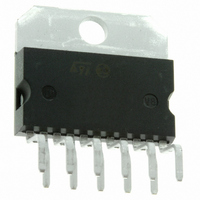
IC DRIVER FULL BRIDGE MULTIWATT
Manufacturer
STMicroelectronics
Type
H Bridger
Specifications of L6203
Input Type
Non-Inverting
Number Of Outputs
2
On-state Resistance
300 mOhm
Current - Output / Channel
4A
Current - Peak Output
5A
Voltage - Supply
12 V ~ 48 V
Operating Temperature
-40°C ~ 150°C
Mounting Type
Through Hole
Package / Case
Multiwatt-11 (Vertical, Bent and Staggered Leads)
Operating Supply Voltage
12 V to 48 V
Supply Current
0.015 A
Mounting Style
Through Hole
Current, Output, High Level
2 mA (Max.)
Package Type
Multiwatt 11
Power Dissipation
2.3 W @ +70°C
Temperature, Operating, Maximum
150 °C
Temperature, Operating, Minimum
-40 °C
Voltage, Input, High Level
2 V (Min.)
Voltage, Input, Low Level
-0.3 V (Min.)
Voltage, Supply
52 V
Motor Type
Full Bridge
No. Of Outputs
2
Output Current
5mA
Output Voltage
60V
Supply Voltage Range
12V To 48V
Driver Case Style
Multiwatt
No. Of Pins
11
Lead Free Status / RoHS Status
Lead free / RoHS Compliant
Other names
497-1421-5
E-L6203
E-L6203
Available stocks
Company
Part Number
Manufacturer
Quantity
Price
Company:

Part Number:
L6203
Manufacturer:
MURATA
Quantity:
30 000


BIPOLAR STEPPER MOTORS APPLICATIONS
Bipolar stepper motors can be driven with one
L6506 or L297, two full bridge BCD drivers and
very few external components. Together these
three chips form a complete microprocessor-to-
stepper motor interface is realized.
Figure 18: Two Phase Bipolar Stepper Motor Control Circuit with Chopper Current Control
Figure 19: Two Phase Bipolar Stepper Motor Control Circuit with Chopper Current Control and Translator
As shown in Fig. 18 and Fig. 19, the controller
connect directly to the two bridge BCD drivers.
External component are minimalized: an R.C. net-
work to set the chopper frequency, a resistive di-
vider (R1; R2) to establish the comparator refer-
ence voltage and a snubber network made by R
and C in series (See DC Motor Speed Control).
L6201
L6201PS
L6202
L6203
L6201
L6201PS
L6202
L6203
L6201
L6201PS
L6202
L6203
L6201
L6201PS
L6202
L6203
L6201 - L6202 - L6203
13/20
Related parts for L6203
Image
Part Number
Description
Manufacturer
Datasheet
Request
R

Part Number:
Description:
STMicroelectronics [RIPPLE-CARRY BINARY COUNTER/DIVIDERS]
Manufacturer:
STMicroelectronics
Datasheet:
Part Number:
Description:
STMicroelectronics [LIQUID-CRYSTAL DISPLAY DRIVERS]
Manufacturer:
STMicroelectronics
Datasheet:

Part Number:
Description:
BOARD EVAL FOR MEMS SENSORS
Manufacturer:
STMicroelectronics
Datasheet:
Part Number:
Description:
NPN TRANSISTOR POWER MODULE
Manufacturer:
STMicroelectronics
Datasheet:
Part Number:
Description:
TURBOSWITCH ULTRA-FAST HIGH VOLTAGE DIODE
Manufacturer:
STMicroelectronics
Datasheet:
Part Number:
Description:
Manufacturer:
STMicroelectronics
Datasheet:
Part Number:
Description:
DIODE / SCR MODULE
Manufacturer:
STMicroelectronics
Datasheet:
Part Number:
Description:
DIODE / SCR MODULE
Manufacturer:
STMicroelectronics
Datasheet:
Part Number:
Description:
Search -----> STE16N100
Manufacturer:
STMicroelectronics
Datasheet:
Part Number:
Description:
Search ---> STE53NA50
Manufacturer:
STMicroelectronics
Datasheet:
Part Number:
Description:
NPN Transistor Power Module
Manufacturer:
STMicroelectronics
Datasheet:
Part Number:
Description:
DIODE / SCR MODULE
Manufacturer:
STMicroelectronics
Datasheet: