L9822EPD STMicroelectronics, L9822EPD Datasheet - Page 14
L9822EPD
Manufacturer Part Number
L9822EPD
Description
IC DRIVER SOLENOID OCT POWERSO20
Manufacturer
STMicroelectronics
Type
Low Sider
Datasheet
1.L9822EPD013TR.pdf
(17 pages)
Specifications of L9822EPD
Input Type
SPI
Number Of Outputs
8
On-state Resistance
550 mOhm
Current - Peak Output
1.05A
Voltage - Supply
4.5 V ~ 5.5 V
Operating Temperature
-40°C ~ 125°C
Mounting Type
Surface Mount
Package / Case
PowerSO-20 Exposed Bottom Pad
Rise Time
50 ns
Fall Time
50 ns
Supply Voltage (min)
- 0.7 V
Supply Current
10 mA
Maximum Operating Temperature
+ 150 C
Mounting Style
SMD/SMT
Minimum Operating Temperature
- 40 C
Number Of Drivers
8
Driver Configuration
Inverting
Driver Type
Low Side
Frequency (max)
2MHz
Operating Supply Voltage (max)
7V
Peak Output Current
1.05A
Operating Supply Voltage (min)
-0.7V
Operating Supply Voltage (typ)
5V
Turn Off Delay Time
10us
Turn On Delay Time (max)
10us
Operating Temp Range
-40C to 150C
Operating Temperature Classification
Automotive
Mounting
Surface Mount
Pin Count
20
Package Type
PowerSO
Lead Free Status / RoHS Status
Lead free / RoHS Compliant
Current - Output / Channel
-
Lead Free Status / Rohs Status
Lead free / RoHS Compliant
Available stocks
Company
Part Number
Manufacturer
Quantity
Price
Company:

Part Number:
L9822EPD
Manufacturer:
ST
Quantity:
5 510
Part Number:
L9822EPD
Manufacturer:
ST
Quantity:
20 000
Part Number:
L9822EPD013TR
Manufacturer:
ST
Quantity:
20 000


Package information
5
14/17
Package information
In order to meet environmental requirements, ST (also) offers these devices in ECOPACK
packages. ECOPACK
is marked on the package and on the inner box label, in compliance with JEDEC Standard
JESD97. The maximum ratings related to soldering conditions are also marked on the inner
box label.
ECOPACK is an ST trademark. ECOPACK specifications are available at: www.st.com.
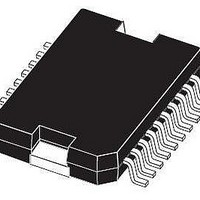
Figure 7.
E1 (1)
(1) “D and E1” do not include mold flash or protusions.
(2) For subcontractors, the limit is the one quoted in jedec MO-166
D1 (2)
D (1)
DIM.
E2
E3
- Critical dimensions: “E”, “G” and “a3”.
a1
a2
a3
e3
- Mold flash or protusions shall not exceed 0.15mm (0.006”)
A
E
G
H
N
S
T
b
c
e
h
L
PowerSO-20 mechanical data and package dimensions
E2
MIN.
0.23
15.8
13.9
10.9
15.5
N
0.1
0.4
9.4
5.8
0.8
h x 45˚
0
0
b
N
11.43
TYP.
20
1.27
mm
1
10
®
packages are lead-free. The category of second Level Interconnect
DETAIL A
MAX.
0.53
0.32
14.5
11.1
15.9
3.6
0.3
3.3
0.1
9.8
2.9
6.2
0.1
1.1
1.1
16
8˚(max. )
8˚(typ.)
e3
D
H
0.004
0.000
0.016
0.009
0.622
0.370
0.547
0.429
0.228
0.000
0.610
0.031
MIN.
1
T
0.050
0.450
0.394
inch
TYP.
11
0
MAX.
0.142
0.012
0.130
0.004
0.021
0.013
0.630
0.386
0.570
0.437
0.114
0.244
0.004
0.626
0.043
0.043
e
a2
E1
A
PSO20MEC
DETAIL B
Weight: 1.9gr
BOTTOM VIEW
R
Gage Plane
a3
MECHANICAL DATA
lead
PowerSO-20
DETAIL B
OUTLINE AND
S
JEDEC MO-166
0.35
D1
E
L
a1
DETAIL A
(COPLANARITY)
E3
slug
c
SEATING PLANE
G C
- C -
0056635 I
L9822E
®
Related parts for L9822EPD
Image
Part Number
Description
Manufacturer
Datasheet
Request
R

Part Number:
Description:
IC DRVR SOLENOID OCT 15MULTIWATT
Manufacturer:
STMicroelectronics
Datasheet:
Part Number:
Description:
MOSFET & Power Driver ICs Octal Ser Solenoid
Manufacturer:
STMicroelectronics
Datasheet:
Part Number:
Description:
STMicroelectronics [RIPPLE-CARRY BINARY COUNTER/DIVIDERS]
Manufacturer:
STMicroelectronics
Datasheet:
Part Number:
Description:
STMicroelectronics [LIQUID-CRYSTAL DISPLAY DRIVERS]
Manufacturer:
STMicroelectronics
Datasheet:

Part Number:
Description:
BOARD EVAL FOR MEMS SENSORS
Manufacturer:
STMicroelectronics
Datasheet:
Part Number:
Description:
NPN TRANSISTOR POWER MODULE
Manufacturer:
STMicroelectronics
Datasheet:
Part Number:
Description:
TURBOSWITCH ULTRA-FAST HIGH VOLTAGE DIODE
Manufacturer:
STMicroelectronics
Datasheet:
Part Number:
Description:
Manufacturer:
STMicroelectronics
Datasheet:
Part Number:
Description:
DIODE / SCR MODULE
Manufacturer:
STMicroelectronics
Datasheet:
Part Number:
Description:
DIODE / SCR MODULE
Manufacturer:
STMicroelectronics
Datasheet:
Part Number:
Description:
Search -----> STE16N100
Manufacturer:
STMicroelectronics
Datasheet:
Part Number:
Description:
Search ---> STE53NA50
Manufacturer:
STMicroelectronics
Datasheet: