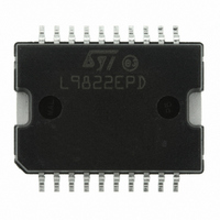
L9822EPD013TR STMicroelectronics, L9822EPD013TR Datasheet - Page 9

L9822EPD013TR
Manufacturer Part Number
L9822EPD013TR
Description
IC DRIVER SOLENOID OCT POWERS020
Manufacturer
STMicroelectronics
Type
Low Sider
Datasheet
1.L9822EPD013TR.pdf
(17 pages)
Specifications of L9822EPD013TR
Input Type
SPI
Number Of Outputs
8
On-state Resistance
550 mOhm
Current - Peak Output
1.05A
Voltage - Supply
4.5 V ~ 5.5 V
Operating Temperature
-40°C ~ 125°C
Mounting Type
Surface Mount
Package / Case
PowerSO-20 Exposed Bottom Pad
Rise Time
50 ns
Fall Time
50 ns
Supply Voltage (min)
- 0.7 V
Supply Current
10 mA
Maximum Operating Temperature
+ 150 C
Mounting Style
SMD/SMT
Minimum Operating Temperature
- 40 C
Number Of Drivers
8
Lead Free Status / RoHS Status
Lead free / RoHS Compliant
Current - Output / Channel
-
Lead Free Status / Rohs Status
Lead free / RoHS Compliant
Other names
497-3660
497-3660-2
497-3660
497-3660-2
497-3660
Available stocks
Company
Part Number
Manufacturer
Quantity
Price
Part Number:
L9822EPD013TR
Manufacturer:
ST
Quantity:
20 000
L9822E
Table 5.
Input buffer (SI, CE, SCLK and RESET pins)
Output buffer (SO pin)
Serial peripheral interface (see
Symbol
t
t
V
wSCKH
V
wSCKL
V
V
C
I
t
V
V
t
t
t
OREF
t
I
t
SOtl
t
t
t
V
f
lead
rSO
t
SOH
t
DIS
fSO
OFF
C
SOL
UD
CC
lag
t
EN
t
rSI
fSI
op
su
ho
I
SO
T–
T+
H
V
H
I
I
Fault refer. voltage
Fault reset delay (after
CE L to H transition)
Output OFF voltage
Threshold voltage at
falling edge SCLK only
Threshold voltage at
rising edge SCLK only
Hysteresis voltage
Input current
Input capacitance
Output low voltage
Output high voltage
Output tristate leakage
current
Output capacitance
Quiescent supply current
at V
Operating frequency
Enable lead time
Enable lag time
Clock high time
Clock low time
Data setup time
Data hold time
Enable time
Disable time
Data valid time
Rise time (SO output)
Fall time (SO output)
Rise time SPI inputs
(SCK, SI, CE)
Fall time SPI inputs
(SCLK, SI, CE)
Output data hold time
Electrical characteristics (continued)
(V
CC
CC
= 5 V ± 5 %. T
Parameter
pin
Figure
j
= – 40 to 125 °C ; unless otherwise specified)
Output progr. OFF
Fault detected if V
See
Output pin floating. Output progr. OFF
V
V
V
V
0 < V
I
I
0 < V
V
0 < V
All outputs progr. ON. I
output simultaneously
V
V
V
V
O
O
5, timing diagram)
CC
CC
T+
CC
CC
CC
CC
CC
CC
= 1.6 mA
= 0.8 mA
– V
Figure
= 5.25 V
= 5 V ± 10 %
= 5 V ± 10 %
= 5.50 V, 0 < V
= 20 to 70 % C
= 70 to 20 % C
= 20 to 70 % C
= 70 to 20 % C
I
O
O
< V
< V
< V
T–
Test Conditions
CC
CC
CC
6.
, CE pin held high,
, CE pin held high
O
I
L
L
L
L
> V
< V
= 200 pF
= 200 pF
= 200 pF
= 200 pF
O
OREF
CC
= 0.5 A per
0.2V
– 1.3V
Min.
0.85
– 20
D.C.
–
V
250
250
200
200
250
250
100
200
200
1.6
0.6
75
75
75
0
CC
10
CC
Electrical specifications
Typ.
0.7V
Max.
4.15
+ 10
250
2.5
0.4
20
20
20
10
50
50
2
1
2
CC
MHz
Unit
mA
µA
µA
pF
pF
µs
ns
ns
ns
ns
ns
ns
ns
ns
ns
ns
ns
ns
ns
µs
V
V
V
V
V
V
V
9/17


