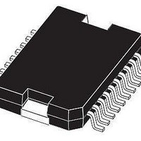
L9930PD13TR STMicroelectronics, L9930PD13TR Datasheet

L9930PD13TR
Specifications of L9930PD13TR
Available stocks
Related parts for L9930PD13TR
L9930PD13TR Summary of contents
Page 1
INTERNAL CLAMPING VOLTAGE = 32V INTERNAL FREE WHEELING DIODES PARALLEL DRIVE CAPABILITY RESISTIVE OR INDUCTIVE LOAD PROTECTION: TEMPERATURE PROTECTION SHORT-CIRCUIT PROTECTION (V GND) DETECTION: SHORTED LOAD OPEN LOAD OVERTEMPERATURE BLOCK DIAGRAM V BAT CHANNEL ...
Page 2
L9930 ABSOLUTE MAXIMUM RATINGS Symbol E Clamped Energy at the Switching off V Continuous Output Voltage out DC V Transient Output Voltage out tr V Continuous Battery Voltage bat DC V Transient Battery Voltage bat tr I Reverse Output Current ...
Page 3
H - BRIDGE CONFIGURATION THERMAL DATA Symbol R Thermal Resistance Junction to Case th j-case R Thermal resistance Junction to Ambient th j-amb ELECTRICAL CHARACTERISTICS (V Symbol Parameter R ON Resistance DSon Resistance DSon-L V Clamping Voltage OCL ...
Page 4
L9930 ELECTRICAL CHARACTERISTICS INPUTS CHARACTERISTICS (normal and standby mode) Symbol Parameter V High Threshold IH V Low Threshold IL I Input Current 1 NHI I Input Current 2 NLO DIAGNOSTIC CHARACTERISTICS V Low Level Voltage DIAGL I Leakage Current DIAGH ...
Page 5
Figure 2: Typical Application VBAT MICRO CONTROLLER Figure 3: Typical Application with Shottky Diodes VBAT MICRO CONTROLLER 22 F VBAT 1K ENABLE 47K 1K IN1 1K IN2 VCC 4.7K 22K DIAG 470pF 22 F VBAT 1K ENABLE 47K 1K IN1 ...
Page 6
L9930 Figure 4: Initialization. IN1 IN2 ENABLE MODE NORMAL DIAG VALID STATUS OUTPUT NORMAL STATUS D96AT308 Figure 5: Normal Condition. IN VBAT Ibranch1 Ibranch2 LOAD Ibranch1 ILOAD Isc D96AT309 GND Iopl Ibranch2 Isc Iopl ILOAD Diag Enable 6/12 STANDBY WAKE-UP ...
Page 7
Figure 6: Short-circuit Condition. IN Isc Ibranch1 Ibranch2 Diag Enable t FILTER Figure 7: short circuit condition: no detection (NOT TESTED) IN Isc Ibranch1 Ibranch2 Diag Enable t< t FILTER t t diagd reset L9930 D96AT311 D96AT312 7/12 ...
Page 8
L9930 Figure 8: Open Load Condition 1: Detection IN Ibranch1 Ibranch2 Iopl1 Iopl2 Diag Enable Figure 9: Open Load Condition 1: No Detection (NOT TESTED) IN Ibranch1 Ibranch2 Iopl1 Iopl2 Diag Enable Figure 10: Open Load Condition 2: No Current ...
Page 9
Figure 11: Open Load Condition 3 IN Ibranch1 Ibranch2 Isc Iopl1 Iopl2 Diag Enable Figure 12: Open Load Condition 4: No Detection IN Ibranch1 Ibranch2 Isc Iopl1 Iopl2 Diag Figure 13: Overtemperature Detection IN temp Diag t sync 160˚C 140˚C ...
Page 10
L9930 mm DIM. MIN. TYP. MAX 2. 0.49 0.55 F 0.88 0.95 G 1.45 1.7 1.95 G1 16.75 17 17.25 H1 19.6 H2 20.2 L 21.9 22.2 22.5 L1 21.7 22.1 22.5 ...
Page 11
DIM. MIN. TYP. MAX. MIN. A 3.6 a1 0.1 0.3 0.004 a2 3 0.1 0.000 b 0.4 0.53 0.016 c 0.23 0.32 0.009 D (1) 15.8 16 0.622 D1 9.4 9.8 0.370 E 13.9 14.5 0.547 e ...
Page 12
... This publication supersedes and replaces all information previously supplied. STMicroelectronics products are not authorized for use as critical components in life support devices or systems without express written approval of STMicroelectronics. © 2003 STMicroelectronics – Printed in Italy – All Rights Reserved Australia - Brazil - Canada - China - Finland - France - Germany - Hong Kong - India - Israel - Italy - Japan - Malaysia - Malta - Morocco - Singapore - Spain - Sweden - Switzerland - United Kingdom - United States ...


