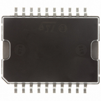
E-L6201PSTR STMicroelectronics, E-L6201PSTR Datasheet - Page 12

E-L6201PSTR
Manufacturer Part Number
E-L6201PSTR
Description
IC DRIVER FULL BRIDGE 20-PWRSOIC
Manufacturer
STMicroelectronics
Type
H Bridger
Datasheet
1.L6201013TR.pdf
(20 pages)
Specifications of E-L6201PSTR
Input Type
Non-Inverting
Number Of Outputs
2
On-state Resistance
300 mOhm
Current - Output / Channel
4A
Current - Peak Output
5A
Voltage - Supply
12 V ~ 48 V
Operating Temperature
-40°C ~ 150°C
Mounting Type
Surface Mount
Package / Case
PowerSO-20 Exposed Bottom Pad
Operating Supply Voltage
5.25 V
Supply Current
11 mA
Mounting Style
SMD/SMT
Lead Free Status / RoHS Status
Lead free / RoHS Compliant
Other names
497-4568-2
Available stocks
Company
Part Number
Manufacturer
Quantity
Price
L6201 - L6202 - L6203
Quiescent Energy
The last contribution to the energy dissipation is
due to the quiescent supply current and is given by:
Total Energy Per Cycle
The Total Power Dissipation P
T
T
T
T
T = Period
T = T
DC Motor Speed Control
Since the I.C. integrates a full H-Bridge in a single
package it is idealy suited for controlling DC mo-
tors. When used for DC motor control it performs
the power stage required for both speed and di-
rection control. The device can be combined with
a current regulator like the L6506 to implement a
transconductance amplifier for speed control, as
shown in figure 17. In this particular configuration
only half of the L6506 is used and the other half
of the device may be used to control a second
Figure 17: Bidirectional DC Motor Control
12/20
r
LD
f
d
= Rise time
= Fall time
= Dead time
= Load drive time
r
+ T
E
E
LD
QUIESCENT
TOT
+ T
+ E
= E
f
ON/OFF
+ T
P
OFF/ON
DIS
d
= I
= E
QUIESCENT
+ E
+ E
TOT
QUIESCENT
LD
/T
DIS
+ E
is simply :
COM
V
s
+
T
motor.
The L6506 senses the voltage across the sense
resistor R
pares the sensed voltage both to control the
speed and during the brake of the motor.
Between the sense resistor and each sense input
of the L6506 a resistor is recommended; if the
connections between the outputs of the L6506
and the inputs of the L6203 need a long path, a
resistor must be added between each input of the
L6203 and ground.
A snubber network made by the series of R and C
must be foreseen very near to the output pins of
the I.C.; one diode (BYW98) is connected be-
tween each power output pin and ground as well.
The following formulas can be used to calculate
the snubber values:
R
C = l
V
the application;
I
dv/dt is the limited rise time of the output voltage
(200V/ s is generally used).
If the Power Supply Cannot Sink Current, a suit-
able large capacitor must be used and connected
near the supply pin of the L6203. Sometimes a
capacitor at pin 17 of the L6506 let the application
better work. For motor current up to 2A max., the
L6202 can be used in a similar circuit configura-
tion for which a typical Supply Voltage of 24V is
recommended.
p
S
is the peak of the load current;
is the maximum Supply Voltage foreseen on
V
p
/(dV/dt) where:
S
/l
p
S
to monitor the motor current: it com-


