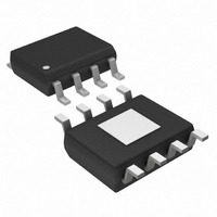
MAX256ASA+ Maxim Integrated Products, MAX256ASA+ Datasheet - Page 12

MAX256ASA+
Manufacturer Part Number
MAX256ASA+
Description
IC DVR H-BRIDGE 3W 8-SOIC
Manufacturer
Maxim Integrated Products
Type
H Bridger
Datasheet
1.MAX256ASA.pdf
(14 pages)
Specifications of MAX256ASA+
Input Type
Non-Inverting
Number Of Outputs
2
On-state Resistance
500 mOhm
Current - Output / Channel
600mA
Current - Peak Output
1A
Voltage - Supply
3 V ~ 5.5 V
Operating Temperature
-40°C ~ 125°C
Mounting Type
Surface Mount
Package / Case
8-SOIC (3.9mm Width) Exposed Pad, 8-eSOIC. 8-HSOIC
Supply Voltage (max)
5.5 V
Supply Voltage (min)
3 V
Maximum Operating Temperature
+ 125 C
Mounting Style
SMD/SMT
Maximum Power Dissipation
1509 mW
Minimum Operating Temperature
- 40 C
Supply Current
1.06 mA
Supply Voltage
5V
Digital Ic Case Style
SOIC
No. Of Pins
8
No. Of Regulated Outputs
2
Operating Temperature Range
-40°C To +125°C
Device Type
Half Bridge
Filter Terminals
SMD
Rohs Compliant
Yes
Lead Free Status / RoHS Status
Lead free / RoHS Compliant
For more information about transformer selection, please
refer to the MAX3535E data sheet. The MAX3535E uses a
transformer in a similar topology. See Tables 3, 4, and 5
in the MAX3535E data sheet for a list of commercially
available transformers. These transformers are preferred
for lower power applications and are suitable for use with
the MAX256 up to the power limits of the transformers.
Alternatively, the MAX256 can drive the primaries of two
or more low-power transformers to provide multiple isolat-
ed outputs. One or more of the manufacturers listed in the
MAX3535E data sheet may produce a custom trans-
former for specific applications. Contact the individual
transformer suppliers for details.
Figure 7. Output Ripple Filter
Figure 8a. +5V to Isolated +5V
Figure 8b. +3.3V to Isolated +5V
12
Low-Power Applications and Multiple Transformers
______________________________________________________________________________________
4.7µF
3W Primary-Side Transformer H-Bridge Driver
4.7µF
47kΩ
470nF
47kΩ
470nF
MODE
CK_RS
CK_RS
MODE
MAX256
+3.3V
25µH
GND
L1
MAX256
+5V
GND
ST2
ST1
OUTPUT
FILTER
ST2
ST1
1:2
C1
2.2µF
1:2.6CT
+5V ISOLATED
0.1µF
0.1
ALL DIODES
MBRS140
+5V
ISOLATED
µF
The high switching speed of the MAX256 necessitates
high-speed rectifiers. Ordinary silicon signal diodes
such as 1N914 or 1N4148 may be used for low-output
current levels (less than 50mA). At higher output cur-
rents, select low forward-voltage Schottky diodes to
improve efficiency. Ensure that the average forward
current rating for the rectifier diodes exceeds the maxi-
mum load current of the circuit. For surface-mount
applications, Schottky diodes such as the BAT54,
MBRS140 and MBRS340 are recommended.
Bypass the supply voltage to GND with a 0.47µF
ceramic capacitor as close to the device as possible.
Additionally, connect a 4.7µF or greater capacitor to
provide input voltage filtering. The equivalent series
resistance (ESR) of the input capacitors is not as criti-
cal as for the output capacitors. Typically, ceramic X7R
capacitors are adequate.
In most applications, the actual capacitance rating of the
output filter capacitor is less critical than the capacitor's
ESR. In applications sensitive to output voltage ripple,
the output filter capacitor must have low ESR. For optimal
performance, the capacitance should meet or exceed
the specified value over the entire operating temperature
range. Capacitor ESR typically rises at low temperatures;
however, OS-CON capacitors can be used at tempera-
tures below 0°C to help reduce output voltage ripple in
sensitive applications. In applications where low output-
voltage ripple is not critical, standard ceramic 0.1µF
capacitors are sufficient.
Figure 8c. +5V to Isolated ±15V
4.7µF
for Isolated Supplies
47kΩ
470nF
CK_RS
MODE
MAX256
+5V
GND
ST2
ST1
1:1.75
Capacitor Selection
Input Bypass Capacitor
Output Filter Capacitor
Diode Selection
0.1µF
0.1µF
ALL DIODES
MBRS140
+5V ISOLATED
-15V ISOLATED
0.1µF
0.1µF


