L6202 STMicroelectronics, L6202 Datasheet - Page 11
L6202
Manufacturer Part Number
L6202
Description
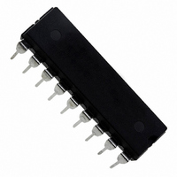
IC DRIVER FULL BRIDGE 18PWRDIP
Manufacturer
STMicroelectronics
Type
H Bridger
Specifications of L6202
Input Type
Non-Inverting
Number Of Outputs
2
On-state Resistance
300 mOhm
Current - Output / Channel
1.5A
Current - Peak Output
5A
Voltage - Supply
12 V ~ 48 V
Operating Temperature
-40°C ~ 150°C
Mounting Type
Through Hole
Package / Case
18-DIP (0.300", 7.62mm)
Operating Supply Voltage
12 V to 48 V
Supply Current
0.015 A
Mounting Style
Through Hole
Current, Output, High Level
2 mA
Package Type
SO20
Power Dissipation
1.3 W
Temperature, Operating, Maximum
150 °C
Temperature, Operating, Minimum
-40 °C
Voltage, Input, High Level
7 V (Max.)
Voltage, Input, Low Level
0.8 V (Max.)
Voltage, Supply
36 V (Typ.)
Lead Free Status / RoHS Status
Lead free / RoHS Compliant
Other names
497-1420-5
Available stocks
Company
Part Number
Manufacturer
Quantity
Price
Company:

Part Number:
L6202
Manufacturer:
STMicroelectronics
Quantity:
1 900
Part Number:
L6202
Manufacturer:
ST
Quantity:
20 000


Boostrap Capacitors
To ensure that the POWER DMOS transistors are
driven correctly gate to source voltage of typ. 10
V must be guaranteed for all of the N-channel
DMOS transistors. This is easy to be provided for
the lower POWER DMOS transistors as their
sources are refered to ground but a gate voltage
greater than the supply voltage is necessary to
drive the upper transistors. This is achieved by an
internal charge pump circuit that guarantees cor-
rect DC drive in combination with the boostrap cir-
cuit. For efficient charging the value of the boos-
trap capacitor should be greater than the input
capacitance of the power transistor which is
around 1 nF. It is recommended that a capaci-
tance of at least 10 nF is used for the bootstrap. If
a smaller capacitor is used there is a risk that the
POWER transistors will not be fully turned on and
they will show a higher RDS (ON). On the other
hand if a elevated value is used it is possible that
a current spike may be produced in the sense re-
sistor.
Reference Voltage
To by-pass the internal Ref. Volt. circuit it is rec-
ommended that a capacitor be placed between its
pin and ground. A value of 0.22 F should be suf-
ficient for most applications. This pin is also pro-
tected against a short circuit to ground: a max.
current of 2mA max. can be sinked out.
Dead Time
To protect the device against simultaneous con-
duction in both arms of the bridge resulting in a
rail to rail short circuit, the integrated logic control
provides a dead time greater than 40 ns.
Thermal Protection
A thermal protection circuit has been included
that will disable the device if the junction tempera-
ture reaches 150 C. When the temperature has
fallen to a safe level the device restarts the input
and enable signals under control.
Figure 16.
APPLICATION INFORMATION
Recirculation
During recirculation with the ENABLE input high,
the voltage drop across the transistor is RDS
(ON) IL, clamped at a voltage depending on the
characteristics of the source-drain diode. Al-
though the device is protected against cross con-
duction, current spikes can appear on the current
sense pin due to charge/discharge phenomena in
the intrinsic source drain capacitances. In the ap-
plication this does not cause any problem be-
cause the voltage spike generated on the sense
resistor is masked by the current controller circuit.
Rise Time T
When a diagonal of the bridge is turned on cur-
rent begins to flow in the inductive load until the
maximum current I
The dissipated energy E
Load Time T
During this time the energy dissipated is due to
the ON resistance of the transistors (E
to commutation (E
DMOS transistors are ON, E
In the commutation the energy dissipated is :
Where :
T
f
Fall Time T
It is assumed that the energy dissipated in this
part of the cycle takes the same form as that
shown for the rise time :
SWITCH
COM
= T
E
= Chopping frequency.
E
E
COM
TURN-ON
ON/OFF
OFF/ON
E
f
r
LD
(See Fig. 16)
LD
= V
(See Fig. 16)
= I
(See Fig.16)
S
= [R
= [R
= T
L
COM
2
L
I
L
TURN-OFF
DS (ON)
DS (ON)
is reached after a time T
R
T
L6201 - L6202 - L6203
). As two of the POWER
DS (ON)
OFF/ON
COM
ON
I
I
L
f
L
SWITCH
2
2
is in this case :
is given by :
2 T
T
T
r
f
] 2/3
] 2/3
LD
LD
T
) and due
LD
11/20
r
.
Related parts for L6202
Image
Part Number
Description
Manufacturer
Datasheet
Request
R

Part Number:
Description:
STMicroelectronics [RIPPLE-CARRY BINARY COUNTER/DIVIDERS]
Manufacturer:
STMicroelectronics
Datasheet:
Part Number:
Description:
STMicroelectronics [LIQUID-CRYSTAL DISPLAY DRIVERS]
Manufacturer:
STMicroelectronics
Datasheet:

Part Number:
Description:
BOARD EVAL FOR MEMS SENSORS
Manufacturer:
STMicroelectronics
Datasheet:
Part Number:
Description:
NPN TRANSISTOR POWER MODULE
Manufacturer:
STMicroelectronics
Datasheet:
Part Number:
Description:
TURBOSWITCH ULTRA-FAST HIGH VOLTAGE DIODE
Manufacturer:
STMicroelectronics
Datasheet:
Part Number:
Description:
Manufacturer:
STMicroelectronics
Datasheet:
Part Number:
Description:
DIODE / SCR MODULE
Manufacturer:
STMicroelectronics
Datasheet:
Part Number:
Description:
DIODE / SCR MODULE
Manufacturer:
STMicroelectronics
Datasheet:
Part Number:
Description:
Search -----> STE16N100
Manufacturer:
STMicroelectronics
Datasheet:
Part Number:
Description:
Search ---> STE53NA50
Manufacturer:
STMicroelectronics
Datasheet:
Part Number:
Description:
NPN Transistor Power Module
Manufacturer:
STMicroelectronics
Datasheet:
Part Number:
Description:
DIODE / SCR MODULE
Manufacturer:
STMicroelectronics
Datasheet: