VN750 STMicroelectronics, VN750 Datasheet - Page 18
VN750
Manufacturer Part Number
VN750
Description
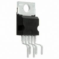
IC DRIVER HI SIDE 6A PENTAWATT
Manufacturer
STMicroelectronics
Type
High Sider
Datasheet
1.VN750-B5.pdf
(44 pages)
Specifications of VN750
Input Type
Non-Inverting
Number Of Outputs
1
On-state Resistance
60 mOhm
Current - Peak Output
6A
Voltage - Supply
5.5 V ~ 36 V
Operating Temperature
-40°C ~ 150°C
Mounting Type
Through Hole
Package / Case
Pentawatt-5 (Vertical, Bent and Staggered Leads)
Supply Voltage (min)
5.5 V
Supply Current
25 mA
Maximum Power Dissipation
60000 mW
Maximum Operating Temperature
+ 150 C
Mounting Style
Through Hole
Maximum Turn-off Delay Time
30000 ns
Maximum Turn-on Delay Time
40000 ns
Minimum Operating Temperature
- 40 C
Number Of Drivers
1
Lead Free Status / RoHS Status
Contains lead / RoHS non-compliant
Current - Output / Channel
-
Lead Free Status / Rohs Status
Lead free / RoHS Compliant
Other names
497-2707-5
Available stocks
Company
Part Number
Manufacturer
Quantity
Price

Company:
Part Number:
VN750B513TR
Manufacturer:
SONY
Quantity:
5 190


Electrical specifications
2.5
2.5.1
18/44
Figure 24. Application schematic
GND protection network against reverse battery
Solution 1: resistor in the ground line (R
This can be used with any type of load.
The following is an indication on how to dimension the R
1.
2.
where - I
maximum rating section of the device datasheet.
Power Dissipation in R
P
This resistor can be shared amongst several different HSDs. Please note that the value of
this resistor should be calculated with formula (1) where I
maximum on-state currents of the different devices.
Please note that if the microprocessor ground is not shared by the device ground then the
R
values. This shift will vary depending on how many devices are ON in the case of several
high side drivers sharing the same R
If the calculated power dissipation leads to a large resistor or several devices have to share
the same resistor then ST suggests to utilize Solution 2 (see below).
D
GND
= (- V
R
R
will produce a shift (I
GND
GND
+5V
µC
CC
GND
)
≤ 600mV / (I
≥ (- V
2
/ R
is the DC reverse ground pin current and can be found in the absolute
GND
CC
R
R
prot
prot
) / (- I
S(on)max
GND
+5V
GND
S(on)max
(when V
)
STATUS
INPUT
).
* R
CC
GND
GND
< 0: during reverse battery situations) is:
.
) in the input thresholds and the status output
V
GND
R
GND
GND
GND
GND
S(on)max
only)
V
CC
resistor.
D
GND
becomes the sum of the
OUTPUT
D
VN750
ld
Related parts for VN750
Image
Part Number
Description
Manufacturer
Datasheet
Request
R

Part Number:
Description:
STMicroelectronics [RIPPLE-CARRY BINARY COUNTER/DIVIDERS]
Manufacturer:
STMicroelectronics
Datasheet:
Part Number:
Description:
STMicroelectronics [LIQUID-CRYSTAL DISPLAY DRIVERS]
Manufacturer:
STMicroelectronics
Datasheet:

Part Number:
Description:
BOARD EVAL FOR MEMS SENSORS
Manufacturer:
STMicroelectronics
Datasheet:
Part Number:
Description:
NPN TRANSISTOR POWER MODULE
Manufacturer:
STMicroelectronics
Datasheet:
Part Number:
Description:
TURBOSWITCH ULTRA-FAST HIGH VOLTAGE DIODE
Manufacturer:
STMicroelectronics
Datasheet:
Part Number:
Description:
Manufacturer:
STMicroelectronics
Datasheet:
Part Number:
Description:
DIODE / SCR MODULE
Manufacturer:
STMicroelectronics
Datasheet:
Part Number:
Description:
DIODE / SCR MODULE
Manufacturer:
STMicroelectronics
Datasheet:
Part Number:
Description:
Search -----> STE16N100
Manufacturer:
STMicroelectronics
Datasheet:
Part Number:
Description:
Search ---> STE53NA50
Manufacturer:
STMicroelectronics
Datasheet:
Part Number:
Description:
NPN Transistor Power Module
Manufacturer:
STMicroelectronics
Datasheet:
Part Number:
Description:
DIODE / SCR MODULE
Manufacturer:
STMicroelectronics
Datasheet: