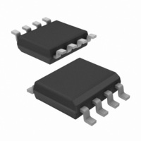
IRS2608DSPBF International Rectifier, IRS2608DSPBF Datasheet - Page 13

IRS2608DSPBF
Manufacturer Part Number
IRS2608DSPBF
Description
IC DVR HALF BRIDGE 600V 8-SOIC
Manufacturer
International Rectifier
Datasheet
1.IRS2608DSTRPBF.pdf
(23 pages)
Specifications of IRS2608DSPBF
Configuration
Half Bridge
Input Type
Differential
Delay Time
250ns
Current - Peak
200mA
Number Of Configurations
1
Number Of Outputs
2
High Side Voltage - Max (bootstrap)
600V
Voltage - Supply
10 V ~ 20 V
Operating Temperature
-40°C ~ 125°C
Mounting Type
Surface Mount
Package / Case
8-SOIC (3.9mm Width)
Lead Free Status / RoHS Status
Lead free / RoHS Compliant
IRS2608DSPbF
Negative V
Transient SOA
S
A common problem in today’s high-power switching converters is the transient response of the switch node’s voltage as
the power switches transition on and off quickly while carrying a large current. A typical 3-phase inverter circuit is
shown in Figure 10; here we define the power switches and diodes of the inverter.
If the high-side switch (e.g., the IGBT Q1 in Figures 11 and 12) switches off, while the U phase current is flowing to an
inductive load, a current commutation occurs from high-side switch (Q1) to the diode (D2) in parallel with the low-side
switch of the same inverter leg. At the same instance, the voltage node V
, swings from the positive DC bus voltage to
S1
the negative DC bus voltage.
Figure 10: Three phase inverter
Figure 11: Q1 conducting
Figure 12: D2 conducting
Also when the V phase current flows from the inductive load back to the inverter (see Figures 13 and 14), and Q4 IGBT
switches on, the current commutation occurs from D3 to Q4. At the same instance, the voltage node, V
, swings from
S2
the positive DC bus voltage to the negative DC bus voltage.
www.irf.com
13


