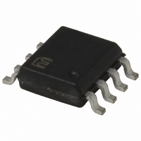
MIC4103YM Micrel Inc, MIC4103YM Datasheet

MIC4103YM
Specifications of MIC4103YM
Related parts for MIC4103YM
MIC4103YM Summary of contents
Page 1
... Micrel’s web site at: www.micrel.com. ___________________________________________________________________________________________________________ Typical Application MLF and MicroLead Frame is a registered trademark of Amkor Technologies, Inc. Micrel Inc. • 2180 Fortune Drive • San Jose, CA 95131 • USA • tel +1 ( November 2010 100V Half Bridge MOSFET Drivers 3/2A Sinking/Sourcing Current Features • ...
Page 2
... Micrel Ordering Information Part Number MIC4103YM MIC4104YM Pin Configuration Pin Description Pin Number Pin Name 1 VDD VSS 8 LO November 2010 Input Junction Temperature Range CMOS TTL 8-Pin SOIC (M) Pin Function Positive Supply to lower gate drivers. Decouple this pin to VSS (Pin 7). Bootstrap diode connected to HB (pin 2) ...
Page 3
Micrel Absolute Maximum Ratings ) ..................... −0.3V to 18V Supply Voltage ( – ........................ −0. Input Voltages ( ............................. −0. Voltage ...
Page 4
Micrel Electrical Characteristics 12V 0V; No load HO Symbol Parameter Bootstrap Diode V Low-Current Forward Voltage DL V High-Current Forward Voltage DH R Dynamic ...
Page 5
Micrel Electrical Characteristics 12V 0V; No load HO Symbol Parameter Switching Specifications (Continued) t Output Rise Time ( Output Fall ...
Page 6
Micrel Timing Diagrams Note: All propagation delays are measured from the 50% voltage level. November 2010 6 MIC4103/4104 M9999-110910-B ...
Page 7
Micrel Typical Characteristics November 2010 7 MIC4103/4104 M9999-110910-B ...
Page 8
Micrel Typical Characteristics (Continued) November 2010 8 MIC4103/4104 M9999-110910-B ...
Page 9
Micrel Functional Characteristics November 2010 Figure 1. MIC4103/4 Functional Block Diagram 9 MIC4103/4104 M9999-110910-B ...
Page 10
Micrel Functional Description The MIC4103 is a high-voltage, non-inverting, dual MOSFET driver that is designed to independently drive both high-side and low-side N-Channel MOSFETs. The block diagram of the MIC4103 is shown in Figure 1. Both drivers contain an input ...
Page 11
Micrel High-Side Driver and Bootstrap Circuit A block diagram of the high-side driver and bootstrap circuit is shown in Figure 4. This driver is designed to drive a floating N-channel MOSFET, whose source terminal is referenced to the HS pin. ...
Page 12
Micrel The value of V should be taken at the peak current F through the diode, however, this current is difficult to calculate because of differences in source impedances. The peak current can either be measured or the value of ...
Page 13
Micrel Application Information The average reverse current and power dissipation due to reverse recovery can be estimated by: = × × × AVE RRM rr = × Pdiode ...
Page 14
Micrel Dissipation during the External MOSFET Turn-On Energy from capacitor C is used to charge up the input B capacitance of the MOSFET (C delivered to the MOSFET is dissipated in the three resistive components and ...
Page 15
Micrel The die temperature may be calculated once the total power dissipation is known. θ × Pdiss J A total JA : where T is the maximum ambient temperatur A ° the junction temperatur ...
Page 16
Micrel Grounding, Component Placement, and Circuit Layout Nanosecond switching speeds and ampere peak currents in and around the MIC4103 and MIC4104 drivers require proper placement and trace routing of all components. Improper placement may cause degraded noise immunity, false switching, ...
Page 17
Micrel C B Vdd HB C VDD Level HO HI shift MIC4103 Vss Figure 11. Synchronous Buck Converter Power Stage Top Side Figure 12. Typical Layout of a Synchronous Buck Converter Power Stage November 2010 A typical ...
Page 18
Micrel Package Information MICREL, INC. 2180 FORTUNE DRIVE SAN JOSE, CA 95131 USA TEL +1 (408) 944-0800 FAX +1 (408) 474-1000 WEB Micrel makes no representations or warranties with respect to the accuracy or completeness of the information furnished in ...


