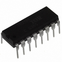
IR2166PBF International Rectifier, IR2166PBF Datasheet - Page 28

IR2166PBF
Manufacturer Part Number
IR2166PBF
Description
IC CONTROLLER PFC/BALLAST 16DIP
Manufacturer
International Rectifier
Type
PFC/Ballast Controllerr
Datasheet
1.IR2166STRPBF.pdf
(32 pages)
Specifications of IR2166PBF
Frequency
39 ~ 50 kHz
Current - Supply
10mA
Current - Output
400mA
Voltage - Supply
11.5 V ~ 15.6 V
Operating Temperature
-25°C ~ 125°C
Package / Case
16-DIP (0.300", 7.62mm)
Package
16-pin DIP
Circuit
Fluorescent Ballast IC
Offset Voltage (v)
600
Output Source Current Min (ma)
250
Output Sink Current Min (ma)
400
Vcc Range (v)
10-25V with UVLO
Output Voltage Min (v)
10
Output Voltage Max (v)
25
Pbf
PbF Option Available
Lead Free Status / RoHS Status
Lead free / RoHS Compliant
Other names
*IR2166PBF
Available stocks
Company
Part Number
Manufacturer
Quantity
Price
Part Number:
IR2166PBF
Manufacturer:
IR
Quantity:
20 000
Ballast Design Equations
Note: The results from the following design
equations can differ slightly from experimental
measurements due to IC tolerances, component
tolerances, and oscillator over- and undershoot
due to internal comparator response time.
Step 1: Program Dead-time
The dead-time between the gate driver outputs
HO and LO is programmed with timing capacitor
CT and an internal dead-time resistor RDT. The
dead-time is the discharge time of capacitor CT
from 3/5VCC to 1/3VCC and is given as:
or
Step 2: Program Run Frequency
The final run frequency is programmed with
timing resistor RT and timing capacitor CT. The
charge time of capacitor CT from 1/3VCC to
3/5VCC determines the on-time of HO and LO
gate driver outputs. The run frequency is
therefore given as:
or
IR2166 & (PbF)
28
f
RUN
R
T
. 1
2
t
C
02
DT
T
C
T
C
(
C
1475
1
. 0
T
t
T
DT
51
f
1475
1
RUN
R
T
2892
1475
[Seconds]
[Farads]
)
[Hertz] (3)
[Ohms] (4)
(1)
(2)
Step 3: Program Preheat Frequency
The preheat frequency is programmed with
timing resistors RT and RPH, and timing
capacitor CT. The timing resistors are
connected in parallel internally for the duration
of the preheat time. The preheat frequency is
therefore given as:
or
Step 4: Program Preheat Time
The preheat time is defined by the time it takes
for the capacitor on pin CPH to charge up to
10 volts. An internal current source of 3uA flows
out of pin CPH. The preheat time is therefore
given as:
or
R
f
PH
PH
C
PH
t
PH
R
2
. 1
T
02
C
T
C
t
. 1
PH
PH
C
1
02
T
. 0
. 3 e
51
0 e
R
C
f
33
1
3 .
PH
T
T
R
1
6
T
f
R
PH
2892
PH
6
R
PH
2892
R
1475
T
[Seconds] (7)
[Farads] (8)
[Ohms] (6)
[Hertz] (5)
www.irf.com


