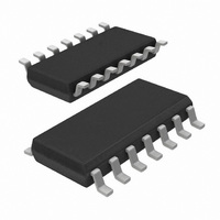
UBA2021T/N2,512 NXP Semiconductors, UBA2021T/N2,512 Datasheet - Page 10

UBA2021T/N2,512
Manufacturer Part Number
UBA2021T/N2,512
Description
IC DRIVER BALLAST CFL/TL 14SOIC
Manufacturer
NXP Semiconductors
Type
CFL/TL Driverr
Datasheet
1.UBA2021PN2112.pdf
(16 pages)
Specifications of UBA2021T/N2,512
Package / Case
14-SOIC (3.9mm Width), 14-SOL
Frequency
41.21 ~ 44.59kHz
Current - Supply
1mA
Voltage - Supply
630V
Operating Temperature
-40°C ~ 150°C
Driver Type
CFL, Fluorescent TL Drivers
Operating Supply Voltage
630 V
Maximum Operating Temperature
+ 150 C
Mounting Style
SMD/SMT
Maximum Output Current
35 mA
Maximum Power Dissipation
500 mW
Minimum Operating Temperature
- 40 C
Supply Current
1 mA
Lead Free Status / RoHS Status
Lead free / RoHS Compliant
Current - Output
-
Lead Free Status / Rohs Status
Lead free / RoHS Compliant
Other names
568-3323-5
935211250512
UBA2021T/N2
935211250512
UBA2021T/N2
Available stocks
Company
Part Number
Manufacturer
Quantity
Price
Part Number:
UBA2021T/N2,512
Manufacturer:
NXP/恩智浦
Quantity:
20 000
NXP Semiconductors
Table 7.
V
[1]
[2]
[3]
[4]
[5]
[6]
[7]
[8]
[9]
11. Design information
UBA2021_4
Product data sheet
Symbol
f
SYM
RR
R
R
ff
VS
CP(sw)
AV
= 11 V; V
The start-up supply current is specified in a temperature (T
current is < 350 A.
The clamp margin is defined as the voltage difference between turn-on of the clamp and start of oscillation. The clamp is in the off-state
at start of oscillation.
Data sampling of V
The total supply current is specified in a temperature (T
current is < 1.5 mA.
Data sampling of V
Within the allowed range of R
Typical values for the on and off resistances at T
The input current at RHV pin may increase to 1600 A during voltage transient at V
550 A is the oscillator frequency proportional to I
The symmetry SYM
and T2
ff
tot
Characteristics
the time between turn-off of G1 and turn-off of G2.
FS
Parameter
feed-forward frequency
symmetry
ripple rejection
CP switch series resistance
averaging resistor
- V
11.1 Design equations
S1
RS(ctrl)
RS(cap)
= 11 V; T
ff
is calculated from the quotient SYM
f
f
•
B
•
•
•
ff
is performed at the end of conduction of T2.
is performed at the start of conduction of T2.
…continued
=
Bottom frequency:
Feed-forward frequency:
Where:
– X1 = 3.68.
– X2 = 22.28.
–
– R
– C
Operating frequency is the maximum of f
=
RREF
amb
----------------------------------------------------------------------------------------------------------------------- -
2
------------------------------------------------------------------------------------------------------------------------- -
2
= 0.4 s.
, defined as 30 k +10 %.
int
par
= 25 C; all voltages referenced to ground; unless otherwise specified. See
= 3 k .
= 4.7 pF
C
C
CF
CF
+
+
Conditions
I
I
I
f
I
I
C
RHV
RHV
RHV
Vin
CP
CP
C
vj
par
RHV
= 87.5 C are: R
par
= 100 Hz
= 100 A
= 10 A
= 0.75 mA
= 1 mA
= 1 mA
Rev. 04 — 25 July 2008
.
vj
) range of 20 C to +125 C. For T
ff
X 1
vj
= T1
1
X 2 V
----------------------------- - R
) range of 0 C to 125 C. For T
1
I
tot
i RHV
R
/ T2
RREF
G2(on)
RREF
tot
, with T1
and R
–
–
R
int
[9]
int
G1(on)
B
tot
, f
the time between turn-off of G2 and turn-off of G1,
+
ff
in
Min
60.4
80.3
0.9
-
0.75
22.4
+
= 164 , R
. Only for currents I
or f
630 V driver IC for CFL and TL lamps
cm
vj
vj
.
< 0 C and T
< 20 C and T
G2(off)
Typ
63.6
84.5
1
6
1.5
32
and R
RHV
vj
>125 C the start-up supply
G1(off)
beyond approximately
vj
UBA2021
>125 C the total supply
© NXP B.V. 2008. All rights reserved.
Max
66.15
88.2
1.1
-
2.25
41.6
= 100 .
Figure
Unit
kHz
kHz
dB
k
k
10 of 16
8.
(1)
(2)


