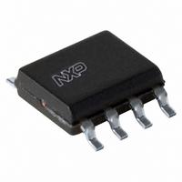
UBA3070T/N1,118 NXP Semiconductors, UBA3070T/N1,118 Datasheet - Page 4

UBA3070T/N1,118
Manufacturer Part Number
UBA3070T/N1,118
Description
IC LED DVR WHITE BCKLGT 8-SOIC
Manufacturer
NXP Semiconductors
Type
Backlight, White LEDr
Datasheet
1.UBA3070TN1118.pdf
(16 pages)
Specifications of UBA3070T/N1,118
Package / Case
8-SOIC (3.9mm Width)
Topology
PWM, Step-Down (Buck)
Number Of Outputs
1
Internal Driver
No
Type - Primary
Backlight
Type - Secondary
White LED
Frequency
145kHz ~ 205kHz
Voltage - Supply
9.3 V ~ 10.6 V
Voltage - Output
12V
Mounting Type
Surface Mount
Internal Switch(s)
Yes
Number Of Segments
2
Low Level Output Current
0.56 uA (Typ)
High Level Output Current
- 0.135 uA (Typ)
Operating Supply Voltage
9.3 V to 10.6 V
Maximum Supply Current
1500 uA
Maximum Power Dissipation
500 mW
Maximum Operating Temperature
+ 145 C
Mounting Style
SMD/SMT
Minimum Operating Temperature
- 40 C
Operating Temperature (min)
-40C
Operating Temperature Classification
Automotive
Package Type
SO
Pin Count
8
Mounting
Surface Mount
Power Dissipation
500mW
Lead Free Status / RoHS Status
Lead free / RoHS Compliant
Operating Temperature
-
Current - Output / Channel
-
Efficiency
-
Lead Free Status / Rohs Status
Compliant
Other names
568-4924-1
NXP Semiconductors
7. Functional description
UBA3070
Product data sheet
7.1 Supply management and UVLO
7.2 Current control and PWM
The UBA3070 is a monolithic driver IC for controlling the current through LED strings e.g.
45 green/blue/white LEDs connected in series making the UBA3070 IC especially suitable
as an LED driver.
The driver stage enables optimal performance for series connected LED strings in 0D, 1D
and 2D segmented Backlight Units (BLUs). Since the UBA3070 drives an external power
device, it can be used for all kinds of BLU designs ranging from high-power to low-power
LEDs, and high-voltage to low-voltage LED strings. Therefore, the UBA3070 is an
excellent driver solution for all types of LEDs and LCD screen sizes. Combining the
UBA3070 with suitable power devices means the quantity of drivers can be minimized by
optimizing the quantity of series LEDs.
Each driver stage consists of a buck converter operating in BCM with its peak level
determined by an external sense resistor. Since the peak and zero levels are fixed by
design, the converter behaves as a current source. This gives an average LED current
throughput that is half the peak value of that through the inductor. The ripple current
through the LEDs can be selected by connecting an external capacitor in parallel with the
LEDs.
As long as V
below 600 μA. The UBA3070 IC activates the converter as soon as the voltage on the V
pin passes the V
voltage typically 8.7 V the UBA3070 IC stops switching.
If the PWM input is HIGH (> 2 V) the converter is disabled and does not switch and, LED
current remains at zero. When the PWM input pin is LOW (< 0.5 V) the converter is
enabled and operates as follows.
The external Field-Effect Transistor (FET) is turned on and current in the inductor begins
to build up. During the charging phase of the inductor the current is sensed across an
external sense resistor. The internal driver turns off the external FET on detecting a
voltage level of 0.52 V at the SENSE pin. The inductor now starts to freewheel its current
through the external diode and starts discharging.
Following the discharge period the switch node rings. On detection of a valley or zero
voltage on the switch node the internal driver turns on the external FET. As the FET is at
zero current and minimal voltage, this results in minimal power losses and
ElectroMagnetic Interference (EMI). The conversion cycle is repeated as described
above, until the PWM input signal is driven high to disable the converter and steers the
LED current to zero.
If the PWM pin is open circuit or not connected, a fault condition is assumed and the
converter stops switching. Operation restarts as soon as the fault condition is removed.
CC
All information provided in this document is subject to legal disclaimers.
is below the V
CC(startup)
Rev. 3 — 9 December 2010
level. When the voltage on V
CC(startup)
level of typically 10 V, the supply current remains
CC
pin drops below the UVLO
LED backlight driver IC
UBA3070
© NXP B.V. 2010. All rights reserved.
4 of 16
CC


