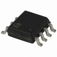
MIC3203-1YM Micrel Inc, MIC3203-1YM Datasheet - Page 12

MIC3203-1YM
Manufacturer Part Number
MIC3203-1YM
Description
IC LED DRIVER CTLR HB 8SOIC
Manufacturer
Micrel Inc
Type
HBLED Driverr
Datasheet
1.MIC3203-1YM.pdf
(21 pages)
Specifications of MIC3203-1YM
Constant Current
Yes
Topology
PWM, Step-Down (Buck)
Number Of Outputs
1
Internal Driver
No
Type - Primary
General Purpose
Type - Secondary
High Brightness LED (HBLED)
Frequency
1.5MHz
Voltage - Supply
4.5 V ~ 42 V
Mounting Type
Surface Mount
Package / Case
8-SOIC (3.9mm Width)
Operating Temperature
-40°C ~ 125°C
Internal Switch(s)
No
Efficiency
90%
Lead Free Status / RoHS Status
Lead free / RoHS Compliant
Voltage - Output
-
Current - Output / Channel
-
Other names
576-3660-5
MIC3203-1YM
MIC3203-1YM
Available stocks
Company
Part Number
Manufacturer
Quantity
Price
Company:
Part Number:
MIC3203-1YM
Manufacturer:
Micrel Inc
Quantity:
135
Inductor
According to the above equation, choose the inductor to
make the operating frequency no higher than 1.5MHz.
The following Tables give a reference inductor value and
corresponding frequency for a given LED current. For
space-sensitive applications, smaller inductor with higher
switching frequency could be used but efficiency of the
regular will be reduced.
Micrel, Inc.
March 2010
RCS (Ω)
RCS (Ω)
RCS (Ω)
0.068
0.068
0.068
1.33
0.56
0.28
0.13
0.08
1.33
0.56
0.28
0.13
0.08
1.33
0.56
0.28
0.13
0.08
Table 4. Inductor for VIN = 36V, 8 LEDs
0.4
0.2
0.1
0.4
0.2
0.1
0.4
0.2
0.1
Table 3. Inductor for VIN = 24V, 4 LEDs
Table 2. Inductor for VIN = 12V, 1 LED
I
I
I
LED
LED
LED
0.15
0.35
0.15
0.35
0.15
0.35
0.5
0.7
1.0
1.5
2.0
2.5
3.0
0.5
0.7
1.0
1.5
2.0
2.5
3.0
0.5
0.7
1.0
1.5
2.0
2.5
3.0
(A)
(A)
(A)
L (µH)
L (µH)
L (µH)
220
100
470
220
150
100
470
220
150
100
68
47
33
22
15
12
10
68
47
33
27
22
68
47
33
27
22
F
F
F
SW
SW
SW
474
439
461
467
475
463
522
522
533
474
426
447
470
493
463
507
496
517
495
446
467
490
515
485
530
519
541
(kHz)
(kHz)
(kHz)
12
Given an inductor value, the size of the inductor can be
determined by its RMS and peak current rating.
where:
I
Select an inductor with saturation current rating at least 30%
higher than the peak current.
MOSFET
MOSFET selection depends upon the maximum input
voltage, output LED current and switching frequency.
The selected MOSFET should have 30% margin on
maximum voltage rating for high reliability requirements.
The MOSFET channel resistance R
that it helps to get the required efficiency at the required LED
currents as well as meets the cost requirement.
Logic level MOSFETs are preferred as the drive voltage is
limited to 5V.
The MOSFET power loss has to be calculated for proper
operation. The power loss consists of conduction loss and
switching loss. The conduction loss can be found by:
L
is inductor average current.
I
I
P
I
D
I Δ
( L
( L
RMS
I
LOSS
L
RMS
PK
=
L
(
)
V
=
FET
)
I =
(
TOTAL
CON
2
=
L
×
)
V
I =
+
V
)
IN
V
I
2
L
I =
LED
CS
_
1
2
CS
+
LED
2
RMS
I Δ
(
(
MAX
12
MAX
1
×
L
(
=
FET
I Δ
)
)
D
. 1
+
-
2
L
V
)
V
09
I ≈
×
CS
CS
I
R
L
L
(
(
MIN
MIN
DSON
)
)
=
DSON
. 0
18
is selected such
M9999-032910-A
MIC3203


