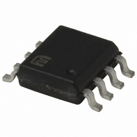
MIC3203-1YM Micrel Inc, MIC3203-1YM Datasheet - Page 11

MIC3203-1YM
Manufacturer Part Number
MIC3203-1YM
Description
IC LED DRIVER CTLR HB 8SOIC
Manufacturer
Micrel Inc
Type
HBLED Driverr
Datasheet
1.MIC3203-1YM.pdf
(21 pages)
Specifications of MIC3203-1YM
Constant Current
Yes
Topology
PWM, Step-Down (Buck)
Number Of Outputs
1
Internal Driver
No
Type - Primary
General Purpose
Type - Secondary
High Brightness LED (HBLED)
Frequency
1.5MHz
Voltage - Supply
4.5 V ~ 42 V
Mounting Type
Surface Mount
Package / Case
8-SOIC (3.9mm Width)
Operating Temperature
-40°C ~ 125°C
Internal Switch(s)
No
Efficiency
90%
Lead Free Status / RoHS Status
Lead free / RoHS Compliant
Voltage - Output
-
Current - Output / Channel
-
Other names
576-3660-5
MIC3203-1YM
MIC3203-1YM
Available stocks
Company
Part Number
Manufacturer
Quantity
Price
Company:
Part Number:
MIC3203-1YM
Manufacturer:
Micrel Inc
Quantity:
135
Application Information
The internal block diagram of the MIC3203 is shown in
Figure 1. The MIC3203 is composed of a current-sense
comparator, voltage and current reference, 5V regulator
and MOSFET driver. Hysteretic mode control – also
called bang-bang control – is a topology that does not
employ an error amplifier, using an error comparator
instead.
The inductor current is controlled within a hysteretic
window. If the inductor current is too small, the power
MOSFET is turned on; if the inductor current is large
enough, the power MOSFET is turned off. It is a simple
control scheme with no oscillator and no loop
compensation. Since the control scheme does not need
loop compensation, it makes a design easy, and avoids
problems of instability.
Transient response to load and line variation is very fast
and only depends on propagation delay. This makes the
control scheme very popular for certain applications.
LED Current and R
The main feature in MIC3203 is to control the LED
current accurately within ±5% of set current. Choosing a
high-side R
current irrespective of wide input voltage range. The
following equation gives the R
For V
Characteristic table.
Micrel, Inc.
March 2010
R
0.068
CS
1.33
0.56
0.28
0.13
0.08
0.4
0.2
0.1
CS(MAX)
(Ω)
R
CS
CS
=
Table 1. R
2
1
resistor helps for setting constant LED
and V
( x
I
LED
0.15
0.35
V
0.5
0.7
1.0
1.5
2.0
2.5
3.0
CS
CS
(A)
(
CS(MIN),
MAX
CS
I
)
LED
for LED Current
+
V
CS
CS
I
refer to the Electrical
2
0.137
value:
R (W)
0.03
0.07
0.1
0.2
0.3
0.4
0.5
0.6
(
MIN
)
)
Size (SMD)
0603
0805
0805
0805
1206
1206
2010
2010
2010
11
Frequency of Operation
To calculate the frequency spread across input supply:
L is the inductance, ∆I
V
For current rising (MOSFET is ON):
where:
V
For current falling (MOSFET is OFF):
where:
where :
•
•
•
•
L
L_RISE
is the voltage across inductor L which varies by supply.
V
V
V
I
LED
D
LED
IN
= V
is Schottky diode forward drop
is input voltage
V
is average LED current
F
T
V
I Δ
t
t
is total LEDs voltage drop
r
SW
f
L_FALL
L
IN
L
=
=
=
=
=
=
L
t
− I
L
r
L
V (
V
V
t +
V
LED
= V
L
I Δ
CS
D
L
t Δ
I Δ
_
f
I Δ
I +
_
(
RISE
L
,
× R
MAX
L
FALL
D
LED
L
F
+ I
SW
R
)
CS
×
L
CS
LED
-
R
is fixed (the value of the hysteresis):
=
V
− V
CS
CS
L
T
× R
1
+
×
LED
(
V
MIN
I Δ
LED
CS
L
×
)
× )
+ V
V (
V (
D
LED
+
IN
V
-
IN
I
LED
)
×
R
CS
M9999-032910-A
-
V
LED
MIC3203
)


